Thursday, 12 July 2018

Plotting temperature over time on a Raspberry Pi

A while back I assembled a temperature measuring system using a DS18B20 temperature sensor which was read by an Arduino fitted with an Ethernet Shield.


To record the temperature over time, I wrote a simple Python program running on a Raspberry Pi 3 to access the Arduino over my local network.

It was not the most elegant of programs, but it recorded the time and temperature into a CSV file.

The CSV file was then opened in Libre Calc, and the results plotted out.


Sunday, 8 July 2018

Programming the BBC micro:bit

One of the simplest methods of programming the micro:bit is using the web based MakeCode by Microsoft.

Here is an example of a "Hello World" program written using MakeCode.

This is the code generated as Javascript.

basic.forever(() => {
    basic.showString("Hello World!")
})

References

BBC micro:bit

The BBC micro:bit is a pocket sized programmable micro-controller designed for use in education.

As part of an education programme, these were given to schoolchildren to be used to teach the principles of programming. They were designed to be compact in size but have an assortment of sensors and feedback devices and to spark the creativity of children to the potential of programming.

After the first distribution, they were made available commercially for all to use.
The commercial version is supplied in a cardboard box containing the micro:bit, a small instruction manual and a safety guide. Minimum additional equipment is required, a USB to micro USB data cable (not a charging cable) and a computer (Windows/Mac/Linux) with a browser.
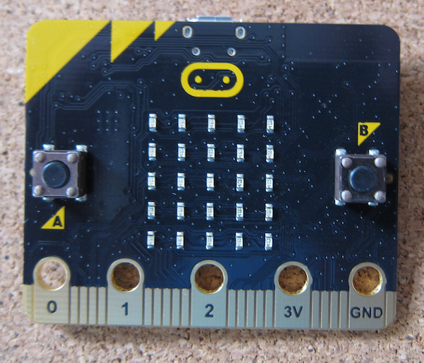
 The rear of the micro:bit, showing the labelling. As you can see it has a Bluetooth Low Energy aerial, magnetometer (compass), accelerometer, micro USB power and data socket, battery connector and processor. It also shows the connectors.
There are five big connectors suitable for crocodile clips, machine screws or conductive thread. On the front face they are labelled pins 0-2, 3V and Ground. Other pins are available through the edge connector. On this side is also the 5 x 5 LED display and two push buttons.

Reference


Use of 32GB+ SD/micro SD cards with the Raspberry Pi

Introduction

The SD and micro SD card are now nearly ubiquitous. Every year the size and speed improve (while the cost only fluctuates).
I use a GoPro camera that takes SD cards, and have recently started to use 64GB cards as that means that I only have to worry about battery life and not running out of storage.
My desktop computer happily reads the cards and allows me to view the photographs and video. While I am away, I take a Raspberry Pi as an entertainment system and to back up my videos. I discovered that my new 64GB card was not visible to the Pi.

SDXC cards (greater than 32GB capacity)

SDXC (Secure Digital eXtended Capacity) extended the capacity of SD format cards beyond the 32GB limit of the previous SDHC (Secure Digital High Capacity) standard. However, they are supplied and assumed to use the proprietary exFAT file system.
Some card readers will always assume that the card will be exFAT format and will treat any other format as defective. This can lead to data loss

Raspberry Pi reading exFAT SDXC cards

Out of the box the Raspbian cannot read SDXC cards formatted with the exFAT filesystem. Due to the patented technologies inherent in any implementation of exFAT, it is not possible to include solutions capable of implementing exFAT in Linux.
However there are solutions within the official repository for Raspbian (and most other Linux distributions).
At the command line or open a terminal window and use the following
Sudo apt-get install exfat-fuse exfat-utils
Restart and you will be able to read your SDXC card and look at the photographs from your camera.

Booting from a 32GB+ SD/Micro SD card

The Raspberry Pi Bootloader can only read FAT and FAT32 cards, and as noted above 64GB and above cards are supplied with the exFAT format.
To use a 64GB card as a boot card it needs to be formatted to FAT32.
The built in disc formatting tools on Linux and MACOS are quite capable of formatting the cards. Make sure to select the FAT32 format.
The case with Windows is slightly different, a third party producr will need to be used as the Windows disc formatter will only format cards greater thn 32GB to exFAT.


References

https://en.wikipedia.org/wiki/Secure_Digital#SDXC
https://en.wikipedia.org/wiki/ExFAT
https://en.wikipedia.org/wiki/ExFAT#Reimplementations
https://www.raspberrypi.org/documentation/installation/sdxc_formatting.md

Tuesday, 3 July 2018

The Sketch That Does Nothing

One of the joys of playing with Arduinos is putting something together, and then taking it apart and building something else.

The various shields sometimes make use of the same pins, and the result of using the previous sketch might be unpredictable.

This sketch literally does nothing, except tell you it does nothing over the serial link.

void setup() {
  // Technology Is Not Dull 2018
  // Use this project to clear sketch from Arduino Board 
  // before fitting a shield so the starting sketch does not 
  // cause any issues with the newly fitted shield.
    Serial.begin(9600);   
    Serial.println("Starting The Project That Does Nothing!");    
    Serial.println("Closing Serial port");
    Serial.end();
}

void loop() {
  // Nothing to see, move along...

}

Sunday, 1 July 2018

GPS Stack - physical build

So this project is to build a simple GPS locator using an Arduino compatible controller, a LinkSprite GPS Shield and a LinkSprite LCD shield.

The specification for the Arduino allows the stacking of shields. What you do need to ensure is that there are no conflicts over pins.

 The controller is the Ciseco Xino RF board.
There is nothing overly important about using this rather than an Arduino UNO, except this board uses a mini USB socket for power so the DC in socket is the highest point.

The GPS shield fits on top. Aligning the pins is a bit worrying as they are a bit delicate and the LinkSprite assembly is a bit squint.
The topping on the stack is the LCD shield.
The alignment issues are clear on the sockets on the photograph above.

Here is the assembled stack.
The DC in socket contacts the


LinkSprite GPS Shield

The LinkSprite GPS shield provides GPS data for Arduino and compatible microcontrollers.
Another purchase from Maplin, this has not particularly good instructions. The photograph on the instructions page is unclear as to how to set up the shorting pins to select the serial port.

The shield takes an SD card, note that due to its advanced age, it only takes SD cards - not SDHC and above. It is a bit difficult to find 2GB cards.

References:

http://linksprite.com/wiki/index.php5?title=GPS_Shield_With_SD_Card_Slot_for_Arduino_V2.0_B

Ciseco Xino RF microcontroller

The Ciseco Xino RF is an Arduino Uno compatible microcontroller with a built in radio module.

Add caption
Maplins stocked the Raspberry Wireless Inventor Kit for the the original Raspberry Pi. It included a Xino RF micro and a matching radio card for the 26 pin connector on the original Raspberry Pi. There was a set in the Maplins closing down sale which was about the same price as an Arduino Uno (but with added LEDs etc) so I added it to my collection (I bought one with my original Model B).

The Xino RF can be used as an Arduino with the added advantage that it uses a Mini USB for power (the DC in port is the highest point on the board, unlike on the UNOs where the USB-A connector with a metal case is the highest point. There is a sketch available that will return it to the Wireless Inventors mode.

LinkSprite LCD Arduino Shield

The LinkSprite 16x2 LCD Shield is a display shield for Arduino compatible microcontrollers.

Maplins (late supplier of electronic bits) stocked a range of LinkSprite products. One of many problems was they had a lot of rather ancient stuff that sat on shelves and was more of interest to archaeologists. With the loss of Maplins, it can be difficult to identify the particular items, but LinkSprite does still have a products wiki here.

Do be aware that the pins used by this LCD shield do not match those on the Arduino examples sketches. To make it more confusing, the example code on the LinkSprite site works (by setting the values in the initialization call) but has not had the pin selection changed in the comments.

If you use the Arduino LCD Shield "HelloWorld" example code, you need to change the pins used :

  •  LCD RS pin to digital pin 8
  •  LCD Enable pin to digital pin 9
  •  LCD D4 pin to digital pin 4
  •  LCD D5 pin to digital pin 5
  •  LCD D6 pin to digital pin 6
  •  LCD D7 pin to digital pin 7
  •  Wiper to LCD VO pin (pin 3)

//const int rs = 12, en = 11, d4 = 5, d5 = 4, d6 = 3, d7 = 2;
const int rs = 8, en = 9, d4 = 4, d5 = 5, d6 = 6, d7 = 7; 

Ensure that the pins are not in use by any other shields or added hardware.

References:

https://www.arduino.cc/en/Reference/LiquidCrystal
http://linksprite.com/wiki/index.php5?title=16_X_2_LCD_Keypad_Shield_for_Arduino_V2
https://www.arduino.cc/en/Tutorial/HelloWorld

Arduino Installation on the Raspberry Pi

Though most software is available on the Raspberry Pi through the use of the APT repository, for some reason the version of the Arduino IDE is rather old, and possibly non standard.

To obtain the latest version you need to grab it from the Arduino web site here.

Follow the instructions and remember to choose the com port.