Showing posts with label Micropython. Show all posts

Thursday, 5 January 2023

Interrupt driven buttons on the Raspberry Pi Pico

There are two ways to detect the operation of buttons - polling and interrupt.

Polling involves checking the status of the button, which has to occur each time and can be missed if the program is busy elsewhere. It does have the benefit of conceptual simplicity.

Interrupts requires the program to be literally interrupted when the button is pressed, and code to be executed and then the program resumes its normal course. There are a number of complexities created by this method, especially if the task is complicated (things can be in the process of being changed when the interrupt occurs and so the results may not be predicted). There are additional complexities involved in the Micropython implementation (see the documentation here)

The PIMORONI Inky Pack (described here) is fitted with three buttons.


The objective is the display details of which button has been pressed.

Each button is attached to a GPIO pin (pins 12-14 on the Inky Pack) and can be created as a simple Pin object using the following code (this is for the button A on the Inky Pack).

pin1 = Pin(12,Pin.IN,Pin.PULL_UP)

To use interrupts, set the trigger and the callback handler function.

pin1.irq(trigger=Pin.IRQ_FALLING, handler=callback)

The callback function 
def callback(pin):

Supplies the Pin object to the code in the function.

Though the Pin object requires the pin id (in this case 12), it is not (currently 05/01/2023) possible to obtain the pin id from the Pin object directly.

However it is possible to check the equivalence of the supplied Pin against known pins:

def callback(pin):
    if(pin == pin1):
        print("Pin 1")

This means the same callback function can be used for all three pins, the equivalence check defines which pin is calling the callback function.

By using the code below, the following text is printed to the REPL console after the three buttons are pressed within the ten second cycle time of the loop and button B is pressed in the next loop.

cycle
Pin 1
Pin 2
Pin 3
cycle
Pin 2

Code

from machine import Pin
import time

# Set pins to the three buttons on the Inky Pack
pin1 = Pin(12,Pin.IN,Pin.PULL_UP)
pin2 = Pin(13,Pin.IN,Pin.PULL_UP)
pin3 = Pin(14,Pin.IN,Pin.PULL_UP)

# Define callback function for the interrupt
def callback(pin):
    if(pin == pin1):
        print("Pin 1")
    if(pin == pin2):
        print("Pin 2")
    if(pin == pin3):
        print("Pin 3")

# Set interrupt trigger and callback handler
pin1.irq(trigger=Pin.IRQ_FALLING, handler=callback)
pin2.irq(trigger=Pin.IRQ_FALLING, handler=callback)
pin3.irq(trigger=Pin.IRQ_FALLING, handler=callback)

# Infinite loop, every ten seconds it prints cycle.
while True:
    time.sleep(10)
    print("cycle")

References


Saturday, 9 July 2022

CircuitPython and MicroPython - – start file differences

CircuitPython and MicroPython have many similarities, but there are some major differences.

One of the most fundamental are the names of the files executed when the board is powered up.

Start up sequence

MIcroPython 

MIcroPython looks for two files in a set order in the root of its filesystem.

  • boot.py – this file is run when power is first applied to the board or when the board is reset. Probably not of interest in general unless you are modifying MicroPython.
  • main.py – this is the file that is either your program or starts your program. If it is present, it is run after the code in the boot.py file.

CircuitPython

CircuitPython looks for the following files in this order:

  • •code.txt
  • •code.py
  • •main.txt
  • •main.py.

References

https://learn.adafruit.com/getting-started-with-raspberry-pi-pico-circuitpython/micropython-or-circuitpython

https://github.com/adafruit/circuitpython#differences-from-micropython

https://docs.circuitpython.org/en/latest/README.html#differences-from-micropython


Sunday, 20 February 2022

PICO Breakout Garden Base

The Pimoroni PICO Breakout Garden Base has a socket for a Raspberry Pi PICO (available from Pimoroni with headers pre-soldered) plus four I2C sockets and two SPI sockets compatible with the Pimoroni breakout garden breakouts. Pimoroni also do a Breakout Garden to QT/QWIIC adapter.


This allows soldering free development (assuming you buy the PICO with headers attached) and reuse of the various breakouts (with other PICOs including the Explorer Base or Raspberry Pis).

There are libraries for C++, MicroPython and Circuit Python.

Installation

Hardware

Breakout Garden Base, self adhesive feet and a Raspberry Pi PICO.
The printed paws on the underside show where the self adhesive feet go.


Before fitting the Raspberry Pi PICO to the Breakout Garden Base, I would recommend testing the PICO. The Blink program (that flashes the PICO's built in LED) is a good test.

The Breakout Garden Base has two rows of sockets to take the pins soldered to the Raspberry Pi PICO microcontroller. Match the orientation of the Pico with the drawing between the sockets and align the pins on the Raspberry Pi PICO with the holes in the sockets and gently and evenly apply pressure until the PICO is in place.

Software

To use the I2C and SPI sockets on the base, Pimoroni have created a custom UF2 file including the required drivers. Follow the instructions here: https://learn.pimoroni.com/tutorial/hel/getting-started-with-pico

If you find the latest Pimoroni UF2 version does not work as expected, use the Update Firmware option on Thonny to return to a vanilla flavour UF2 and reload the Blink example.

It might be that the latest version has introduced a bug in the Breakout Garden handling. Download and install an earlier version of the Pimoroni UF2.

It is very useful to add parts of the Blink example to your code when testing to show that the code is working.

There are examples for a number of the breakouts available.

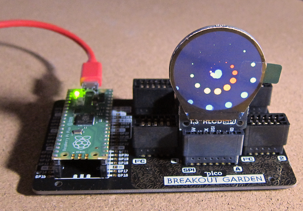
1.3" SPI Colour Round LCD example in operation.

References

https://shop.pimoroni.com/products/pico-breakout-garden-base

https://shop.pimoroni.com/products/raspberry-pi-pico?variant=32402092326995

https://shop.pimoroni.com/collections/breakout-garden

https://shop.pimoroni.com/products/breakout-garden-to-qwiic-adaptor

https://en.wikipedia.org/wiki/I%C2%B2C

https://en.wikipedia.org/wiki/Serial_Peripheral_Interface

https://learn.pimoroni.com/tutorial/hel/getting-started-with-pico

https://github.com/pimoroni/pimoroni-pico/releases

https://github.com/pimoroni/pimoroni-pico/tree/main/micropython/examples


Monday, 17 January 2022

Raspberry Pi Pico Explorer

The Raspberry Pi Pico Explorer is a plug-in board that provides a number of built-in devices including a 240x240 colour display, four buttons, a piezo buzzer, two I2S Breakout Garden sockets and sockets connected to the Pico's pins plus a small solderless breadboard.

A Raspberry Pi Pico with pre-soldered headers makes development easy without needing to solder delicate electronics.


Assembly was easy, care being taken to make sure all the pins aligned with the corresponding holes in the socket on the board.

Updating the Firmware

To use the components on the Explorer board, Pimoroni has created a custom UF2 file, including the required drivers. As of 03/01/2022 the latest version of the Pimoroni firmware (0.3.2) does not work, use version 0.3.1. This might not be the case for other boards.

Use the Update Firmware option on Thonny to return to a vanilla flavour and the Blink example if the current Pimoroni version does not work as expected. Select an earlier version of the UF2 and try again.

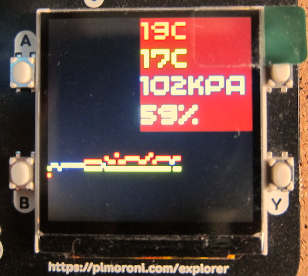
There is an example that measures the cpu temperature which is then displayed as text and a bar graph.
The next stage was to make use of the Breakout Garden sockets and add some breakout units. 
To provide some measurements, a BME680 environmental sensor was added to the right hand socket. In the left hand socket is a rotary encoder with a built in RGB LED.
The two sockets allow the addition of two breakouts. PIMORONI have a range of breakouts, including additional convertors that allow connection to STEMMA or Qwiic devices.

The BME680 breakout is an older model, the current version includes a built in STEMMA or Qwiic connector.
The example program was modified to get the temperature, pressure and humidity from the BME680 sensor plus the cpi temperature.

The code to set the encoder's RGB LED colour was also added.
The graph code was designed to display both the cpu temperature and the sensor temperature.

Finally a maximum and minimum sensor temperature was added to the display.

Code

Do check the indenting as Python uses the indenting to define the structure of the program.

import machine
import utime

from breakout_bme68x import BreakoutBME68X
from pimoroni_i2c import PimoroniI2C

PINS_BREAKOUT_GARDEN = {"sda": 4, "scl": 5}
PINS_PICO_EXPLORER = {"sda": 20, "scl": 21}

i2c = PimoroniI2C(**PINS_PICO_EXPLORER)

# Pico Explorer boilerplate
import picoexplorer as display
width = display.get_width()
height = display.get_height()
display_buffer = bytearray(width * height * 2)
display.init(display_buffer)

# BME68x configuration
bme = BreakoutBME68X(i2c)
#bme.configure(FILTER_COEFF_3, STANDBY_TIME_1000_MS, OVERSAMPLING_16X, OVERSAMPLING_2X, OVERSAMPLING_1X)

# reads from Pico's temp sensor and converts it into a more manageable number
sensor_temp = machine.ADC(4)
conversion_factor = 3.3 / (65535)

# Set up text areas
blockHeight = 33
textBlocks = 8
textArea=list()
for x in range(textBlocks):
    if(textBlocks>4):
        if(x<4):
            textArea.append([10,(blockHeight*x)+1,120,blockHeight])        
        else:
            textArea.append([120,(blockHeight*(x-4))+1,120,blockHeight])
    else:
        textArea.append([120,(blockHeight*x)+1,120,blockHeight])

# Set up background and text pens
background_pen = display.create_pen(0,0,0)
cpu_temp_pen = display.create_pen(255, 64, 64)
bme_temp_pen = display.create_pen(64, 255, 64)
pressure_pen = display.create_pen(64, 64, 255)
humidity_pen = display.create_pen(0, 255, 255)

# Define number of pixels for the graph points
graph_element_size = 1
graph_y_scale = 4

def drawTemp(i,cpu_temp,sensor_temp):
    diff = abs((cpu_temp*graph_element_size)-(sensor_temp*graph_element_size))
    if(diff<graph_element_size):
        display.set_pen(255,255,0)
        display.rectangle(i, height - (cpu_temp * graph_y_scale), graph_element_size,graph_element_size)
    else:
        display.set_pen(cpu_temp_pen)
        display.rectangle(i, height - (cpu_temp * graph_y_scale), graph_element_size,graph_element_size)
        display.set_pen(bme_temp_pen)
        display.rectangle(i, height - (int(sensor_temp) * graph_y_scale), graph_element_size,graph_element_size)
    
def writeInBlock(text, location, pen, paper, size):
    # Draw background to clear display area
    display.set_pen(paper)
    display.rectangle(location[0],location[1],location[2],location[3])
    # Write text in location one pixel left and down
    display.set_pen(pen)
    display.text(text, location[0]+1,location[1]+1,100,size)
    
# Initialise run variables
i = 0
count = 0
max_temp = 0
min_temp = 100

while True:
    # the following two lines do some maths to convert the number from the temp sensor into celsius
    reading = sensor_temp.read_u16() * conversion_factor
    temperature = round(27 - (reading - 0.706) / 0.001721)
    bmetemp, pressure, humidity, gas_resistance, status, gas_index, meas_index = bme.read()
    max_temp=max(max_temp,bmetemp)
    min_temp=min(min_temp,bmetemp)
    
    # Clear the display and reset counter if the graph reaches the right hand side
    if i >= (width + 1):
        i = 0
        display.set_pen(0, 0, 0)
        display.clear()

    # Draw graph element
    drawTemp(i,temperature,bmetemp)

    writeInBlock("{:.0f}".format(temperature) + "c", textArea[0],cpu_temp_pen,background_pen,4)
    writeInBlock("{:.0f}".format(bmetemp) + "c", textArea[1],bme_temp_pen,background_pen,4)
    writeInBlock("{:.0f}".format(pressure/1000) + "kPa", textArea[2],pressure_pen,background_pen,3)
    writeInBlock("{:.0f}".format(humidity)+"%", textArea[3],humidity_pen,background_pen,4)
    writeInBlock("Mx {:.0f}".format(max_temp) + "c", textArea[4],bme_temp_pen,background_pen,3)
    writeInBlock("Mn {:.0f}".format(min_temp) + "c", textArea[5],bme_temp_pen,background_pen,3)
    # time to update the display
    display.update()

    # waits for 5 seconds
    utime.sleep(1)

    # Set next graph element location
    i+=graph_element_size


Saturday, 12 June 2021

Raspberry Pi Pico and MicroPython

Installing MicroPython


To install or upgrade MicroPython on a Pico there are three steps.

1. Download the UF2 file. There is a vanilla version available from micropython.org, or if you are using one of Pimoroni's boards then you can select one of the UF2 files with all their libraries preinstalled here.

2. Put the Pico into BootLoader mode by unplugging it, hold the BOOTSEL button down and then plugging it back in. The Pico will then appear as a USB device on the host machine.

3. Copy the UF2 file into the new USB device

Once the file has been copied over, the USB device will disappear.

Testing the MicroPython

As the Pico has no built-in display, it can only communicate via the USB. The MicroPython firmware has a built-in serial port available over the USB.

To access it, the popular Minicom package is used.

Install it on your Pi using:

sudo apt install minicom

Next, identify the serial port.

The Pico should appear as a port of the form /dev/ttyACM.

Use 

ls /dev/tty*

If it is unclear which port is the Pico, unplug it and try again, identifying which device disappears.

Connect to the MicroPython running on the Pico using:

minicom -o -D /dev/ttyACM0

This should display the Minicom opening text:

Welcome to minicom 2.7.1
OPTIONS: I18n 
Compiled on Aug 13 2017, 15:25:34.
Port /dev/ttyACM0, 07:39:31
Press CTRL-A Z for help on special keys

You now need to soft reboot, press Control and D. This will display information about the installed MicroPython and the prompt >>>.

MPY: soft reboot

MicroPython v1.15 on 2021-04-18; Raspberry Pi Pico with RP2040

Type "help()" for more information.

>>>

To test the MicoPython, try the classic:

>>> print("hello")

hello

>>>

This shows that MicroPython is running successfully on your Pico.

Control A then Z brings up help.

Control X closes Minicom.

References

https://micropython.org/download/rp2-pico/rp2-pico-latest.uf2

https://github.com/pimoroni/pimoroni-pico/releases

https://datasheets.raspberrypi.org/pico/raspberry-pi-pico-python-sdk.pdf

https://en.wikipedia.org/wiki/Minicom


Friday, 5 February 2021

Raspberry Pi Pico part two

 So I ordered a Raspberry Pi Pico from Pimoroni (before picking one up on the cover of Hackspace).

It came in its own little box from a reel.

Here are the two Picos.

And a comparison with the Rapspberry Pi Zero.

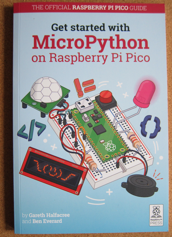
And if you want to program it in Micropython, Raspberry Pi Foundation has a book. It is available as a physical book or as a free PDF.


Sunday, 24 January 2021

Raspberry Pi Pico Microcontroller

 Raspberry Pi have just released a new product into a new market for them a low cost microcontroller. And not just a microcontroller using an existing piece of silicon, no, this is a in-house custom designed processor.

Why a microcontroller?

General purpose computers like the Raspberry Pi are great at doing lots of things, but that comes at a price. They can do lots of things that appear to humans  to be happening at the same time, but it is like juggling, if you are late getting to one of the items in the air, one or more of the items is going to come crashing down. By dedicating a microcontroller to the task, you can ensure the timely response.

Also, because microcontrollers do not have to contain all the clever hardware to handle lots of memory, task swapping and other things required for general purpose computers they are both economical in cost and energy requirements.

There are plenty of microcontrollers about such as the BBC Microbit and Arduino (and compatible), but most are built using an existing System On A Chip.

Raspberry Pi decided to build a dedicated microcontroller chip based on their experiences with the Sense Hat and the all in one Raspberry Pi 400.

What does Raspberry Pi Pico look like?


As you can see, it is much smaller than even the Raspberry Pi Zero (a WH example above). 

Out of the box it has only limited built in semsors and outputs, this is not a Circuit Playground Express.

Basically it has a green LED on GPIO pin 25 and a chip temperature sensor.

What is it for?

The Raspberry Pi Pico can be used where other microcontrollers would be used. It lacks the existing Arduino Shield eco-system, so generally where it is the basic I/O that is required.

It is small, and frugal with the power so it can run independently on two or three AA batteries.

How do you get one?

They are available from the usual suspects, I have one on order from Pimoroni.
In addition, they are on the cover of issue 39 of the print version of the Hackspace magazine.


What can you program it in?

At the moment there is a full C/C++ SDK and ports of Micropython and CircuitPython.
There is currently no Arduino implementation, but there will be an official RP2040 based Arduino device so I suspect that will not be a long wait.

Raspberry Pi RP2040

There is a full description of the RP2040 here, but these are the highlights:

  • In-house design using dual core ARM Cortex M0+
  • 264KB RAM
  • Upto 16MB of external Flash memory via a QSPI bus.
  • 30 GPIO pins (four owhich can be configured as analogue input)
  • Two each of UART, SPI and I2C controllers
  • 16 PWM channels
  • USB host and device support plus mass-storage boot mode for drag and drop programming
  • Eight Programmable I/O state machines

The eight PIO state machines are a particular innovation - they are programmable in a simple assembly language to perform tasks at set rates. Each instruction takes one cycle and is independent of the two main cores. This allows you to set up time sensitive operations at known speeds, irrespective of what the main processor is doing. Most microcontrollers would require bit-banging, using the processor to transmit or receive data by changing/reading the state of an input. The PIO allows this to be offloaded to a PIO with full control of the process. All the processor has to do is ensure that it is kept fed or emptied in time.

The chip is called an RP204 based on a naming system:

Cores: 2

CPU type: 0 ~ M0 - this is a loose description of the CPU type.

RAM: 4  = floor(log2(ram / 16k))

Flash: 0 = floor(log2(nonvolatile / 16k)) or zero in this case (the host board provides the Flash storage).

The Future

There are a range of products from Pimoroni, Adafruit, SparkFun and Arduino planned to use the RP2040, so we shall see.

References


Sunday, 14 June 2020

BBC Micro:Bit Menu system (with persistent choice)

The BBC Micro:Bit is a simple microcontroller with a 5 x 5 matrix of LEDs, two buttons, 3D magnetic and acceleration sensors and a CPU temperature sensor.
The two buttons can make complicated interfaces rather difficult, however it is possible to build one.
One aadditional feature of this menu system is that your choices are persistent. If you select menu item, power off the Micro:Bit then subsequently power it back one, it will remember the choice (subject to it not being reflashed of course).

Code

This was written in Micropython using the Mu editor.
from microbit import *
import os
import utime
menuitem = 0
if 'choice.opt' in os.listdir():
    with open('choice.opt') as choice:
        menuitem = int(choice.read())
display.scroll("Menu item" + str(menuitem))
start = utime.ticks_ms()+6000
interval = 2000
while True:
    now = utime.ticks_ms()
    if start > now or now - start > interval:
        if menuitem == 0:
            temp = temperature()
            interval = 2000
            display.scroll(str(temp) + 'C', delay=100, wait=False)
        elif menuitem == 1:
            temp = temperature()
            interval = 2000
            display.scroll(str(temp + 273.15) + 'K', delay=100, wait=False)
        elif menuitem == 2:
            level = display.read_light_level()
            interval = 2000
            display.scroll(str(level) + ' light', delay=100, wait=False)
        elif menuitem == 3:
            level = compass.get_field_strength()
            interval = 6000
            display.scroll(str(level) + ' nTesla', delay=100, wait=False)
        elif menuitem == 4:
            display.scroll("Menu test")
        start = now 
    if button_a.is_pressed():
        display.scroll("Menu", delay = 100)
        sleep(50)
        while not button_a.is_pressed():
            display.set_pixel(4,menuitem,5)
            if button_b.is_pressed():
                display.set_pixel(4,menuitem,0)
                menuitem = menuitem + 1
                if menuitem > 4:
                    menuitem = 0
                with open('choice.opt','w') as choice:
                    choice.write(str(menuitem))
                display.scroll("Menu item" + str(menuitem), delay = 100)
            sleep(100)
            display.set_pixel(4,menuitem,5)
            sleep(100) 
    sleep(400)
The persistent choice is handled by this code:
menuitem = 0
if 'choice.opt' in os.listdir():
    with open('choice.opt') as choice:
        menuitem = int(choice.read())
The menu item is given a default value (0).
The file 'choice.opt' is checked if it exists in the directory list, if it is, then the value of the menu item is read from the file and assigned to the menuitem variable. When a subsequent decision is made to change the menuitem, this value is written out to the file, making it available the next time the Micro:Bit is switched on.

The main loop is entered after the start variable is set in advance of the current tick count and the display interval is set (strictly speaking the interval should be dependent on the menu choice but it only affects the first cycle).

Each loop, if the difference between the ticks now and the (loop) start ticks is greater than the interval, then the menuitem is used to choose what to do.
In this example it is used to choose which sensor is read and the results displayed.
Menu choices are:

  1. Temperature in degrees Celsius.
  2. Temperature in Kelvin
  3. Light level (based on the light falling on the LED matrix)
  4. Magnetic field strength in nanoTesla (using the compass module)
  5. A message.
The first three keep the interval at two seconds, but the magnetic field strength is a longer piece of text, so that is stretched to six seconds by setting the interval.
The Start ticks value is set to the Now value.

The next part of the code checks for the A button (left side) being pressed.
If so, it then loops until the button is pressed again.
Inside that loop, pressing the B (right hand) button increments the menuitem value, writes it to the file and shows a pixel on the right hand column indication which option is currently chosen.
Pressing button A exits the loop and recommences the outer infinite loop.

Disadvantages

This does mean that during normal operation, button A is not available. This might not be an issue but is something to bear in mind.

References


Saturday, 13 June 2020

Pimoroni Envirobit

Pimoroni Envirobit


The Pimoroni Envirobit is a set of sensors for the BBC Micro:Bit .


As you can see, it is equipped with a slot to take the Micro:Bit, so no soldering is required.

The Envirobit is fitted with the following sensors:

  • BME280 environmental sensor - which measures temperature, pressure, humidity and can calculate the altitude based on a supplied base pressure level (discuss).
  • tcs3472 RGB sensor - which measures Red Green and Blue light levels as well as “white” light levels. Also includes two illuminating (white) LEDs,
  • Sound - a small microphone allows the sound level to be measured on one of the Micro:Bit’s analogue pins

Assembly

Assembly is simple. Take the Envirobit board with the sensors facing forward, and insert the Micro:Bit with the LEDs also facing forward.
Due to the nature of the connection, you can swap the Microbits if the colour scheme does not match your needs.

Software

The main software support for the Envirobit is orientated towards the Microsoft MakeCode block based system.
There is some support for MicroPython. There is a GitHub link here: https://github.com/pimoroni/micropython-envirobit

There are three python files in the Library.
  • sound.py
  • bme280.py
  • tcs3472.py

The files can be transferred to your Micro:Bit using the Files function in Mu.

Sound

Contrary to the description on GitHub, this is not a class, just three methods.

  • sound.read() - This takes a reading of the sound level and returns a value between 0 and 440. There is an offset value in the code to set the minimum sensitivity.
  • sound.wait_for_double_clap() - listen for two high level sound events in a second, returns True if detected
  • sound.wait_for_clap() - listen for a single high sound level event in a second, returns True if detected

tcs3472

This uses a class to access the TCS3472 sensor via I2C.
To use the sensor, import the module (having transferred it to the Micro:Bit) and instantiate an instance.
import tcs3472
light_sensor = tcs3472.tcs3472() 
Methods:

  • r, g, b = light_sensor.rgb() - returns a tuple of the corrected levels of red, green and blue out of 255
  • r, g, b = light_sensor.scaled() - return a tuple of the amounts of red, green and blue on a scale of 0-1
  • level = light_sensor.light() - return a raw reading of light level on a scale of 0-65535
  • light_sensor.set_leds(0) - Turn the LEDs off
  • light_sensor.set_leds(1) - Turn the LEDs on

BME280

This uses a class to access the BME280 sensor via I2C.
The instructions on GitHub are incorrect, there is a missing () on the end of the class instantiation. Python can be very unforgiving if you make a mistake of this kind.
import bme280
bme = bme280.bme280()

The bme280 class has the following methods:

  • temp = bme.temperature() - return the temperature in degrees C
  • pressure = bme.pressure() - return the pressure in hectopascals
  • humidity = bme.humidity() - return the relative humidity in %
  • alt = bme.altitude() - return the altitude in feet, calculated against the current QNH value
  • bme.set_qnh(value) - set the QNH value for calculating altitude

QNH is the atmospheric pressure adjusted to sea level (what the pressure sensor should read at sea level).
https://en.wikipedia.org/wiki/QNH

References

https://github.com/pimoroni/micropython-envirobit
https://en.wikipedia.org/wiki/QNH


Sunday, 24 May 2020

Micro:bit Beacon - part 1: the beacon

One of the features of the Micro:Bit is its Bluetooth compatible radio.

Unfortunately, it is not available in Micropython due to the size of the Bluetooth software stack.

Whatt is available is a Radio object which uses the radio hardware to communicate between Micro:bits.

There is a neat program on the documentation site called Firefly. This has groups of Micro:bits communicating with each other.

Now this project uses the "flash" technique from the Firefly project.

from microbit import *
import radio
import utime
import machine

# "Flash" effect from the Firefly program
#https://microbit-micropython.readthedocs.io/en/latest/tutorials/radio.html?highlight=Firefly#fireflies
flash = [Image().invert()*(i/9) for i in range(9, -1, -1)]

# Obtain the machine id
machineID=machine.unique_id()

# Flash the display over a half second 
# and send the machine ID every second.
while True:
        display.show(flash, delay=50, wait=False)
        radio.on()
        radio.send(str(machineID))
        sleep(500)
        radio.off()
        sleep(500)


Wednesday, 19 September 2018

CircuitPython: writing to the file system.

Circuitpython has a very easy way of uploading code and data to the microcontroller, the microcontroller's storage appears as a USB storage device on the host's operating system. To move code and data to the microcontroller, you simply copy everything to the volume.

Unfortunately this does mean that, by default, Circuitpython cannot write data to its own storage (it is read only) and so it cannot write data that will visible to the host.

However it is possible to change that in the optional boot.py code file.

The boot.py file is only run on the first boot of the device (power up) and not when REPL is restarted or when you save a file. The microcontroller needs to be Ejected as a USB device and the reset button pressed.

Note: When you change it from read only, it is not possible to update the code on the microcontroller - including the boot.py.

The boot.py file needs to contain the following code:
import storage
storage.remount("/", False)

The first line imports the storage module, allowing access to OS functions.
The second line remounts the storage with readonly set to false.

The boot.py file can be "removed" via REPL (Read - Evaluate - Print - Loop). This is very like a command line interface combined with an (xPython) interpretor.

To access REPL on Mu:
Click on the Serial button on the ribbon. This will open a serial connection to the connected microcontroller.
Press CTRL-C (keyboard interrupt) to stop CircuitPython from continuing with whatever it is doing.
Press any key (as instructed).
Use the REPL.

To remove the boot.py, you need to rename the file via REPL:
import os
os.listdir("/")
os.rename("/boot.py", "/boot.bak")

The first line imports the storage module, allowing access to OS functions.
The second lists the contents of the root of the microcontoller's storage.
The third renames the boot.py file to boot.bak.

The microcontroller needs to be ejected (as a USB device) and the reset button pressed (physically unplugging it after ejecting it will also work).

References

https://codewith.mu/en/tutorials/1.0/repl
https://learn.adafruit.com/cpu-temperature-logging-with-circuit-python/writing-to-the-filesystem
https://circuitpython.readthedocs.io/en/2.x/shared-bindings/storage/__init__.html

MU Python, Micropython and CircuitPython editor

The Micro:bit can be programmed offline using the Mu editor. Until recently the editor available on the Raspbian repository has been an earlier version without support for the Radio module.

For a Raspberry Pi, Mu is now included in the Recommended Software option.

Instructions for installation are listed in the references.

References:

https://codewith.mu/
https://www.raspberrypi.org/blog/mu-python-ide/
https://projects.raspberrypi.org/en/projects/getting-started-with-mu