Showing posts with label Microcontroller. Show all posts

Saturday, 8 October 2022

Raspberry Pi Pico W


In June 2022 Raspberry Pi released a version of their Pico microcontroller with WiFi (and theoretucakky Bluetooth) capability.

The main pinout is identical, but the placement of the aerial required the debug pins be moved.


Saturday, 9 July 2022

CircuitPython and MicroPython - – start file differences

CircuitPython and MicroPython have many similarities, but there are some major differences.

One of the most fundamental are the names of the files executed when the board is powered up.

Start up sequence

MIcroPython 

MIcroPython looks for two files in a set order in the root of its filesystem.

  • boot.py – this file is run when power is first applied to the board or when the board is reset. Probably not of interest in general unless you are modifying MicroPython.
  • main.py – this is the file that is either your program or starts your program. If it is present, it is run after the code in the boot.py file.

CircuitPython

CircuitPython looks for the following files in this order:

  • •code.txt
  • •code.py
  • •main.txt
  • •main.py.

References

https://learn.adafruit.com/getting-started-with-raspberry-pi-pico-circuitpython/micropython-or-circuitpython

https://github.com/adafruit/circuitpython#differences-from-micropython

https://docs.circuitpython.org/en/latest/README.html#differences-from-micropython


Sunday, 2 January 2022

WIZnet W5100S-EVB-Pico Ethernet microcontroller

 The W5100S-EVB-Pico microcontroller board is pin compatible with the Raspberry Pi Pico and uses the same RP2040 microcontroller. It is integrated with the WIZnet W5100S ethernet controller.


It has a built in RJ45 ethernet socket.

There are examples in Circuit Python and C/C++.

As an exercise I decided to first try using C/C++ as the development language and a Windows 10 machine as the development machine (cross compiling to the ARM based RP2040).

I followed the instructions to install CMAKE, however there is an ongoing issue with CMAKE version 3.21+ that causes a 

AR10B2~1.EXE: error: n++CMakeFiles/blink.dir/blink.c.obj: No such file or directory

error when executing the nmake line of the instructions.

It is suggested that an earlier version of the CMAKE tool is installed. Version 3.20 seems to work. 

I tested the basic operation of the board by using the Blink example from the Raspberry Pi Pico examples.

WIZnet examples

The instructions for retrieving the examples from WIZnet are not quite as clear.
Eventually I managed to GIT clone the files. However it was quite difficult to get it to actually compile because of the folder structure.

In the end I started from scratch with a new folder structure and copied the files as required.

The default compiler for CMake needs to have been set (I ended up setting it via Visual Studio Code).

Initially the Blink example was included as I knew that worked. Once that worked, the CMakeLists.txt file was edited to include all the components required (see example below).

This included the patches files. Unfortunately that failed with an incorrect version error.

Compiling without the patches lead to pages of missing methods errors.
Examining the first patch file highlighted the change being made, selection of the Ethernet device chip set. The supplied code selects the W5500 chip set - the rest of the code only contains the W5100S chip set code, it is not selected and so methods are missing.

Manually updating the chip selection (as shown in the patch file) to the W5100S chip set solved the issue with the missing methods.

Once compiled, the EVB was put into bootloader mode and the UF2 was copied over.

Attempting to browse to the machine based on the default IP address failed.

The default IP address {192, 168, 11, 2} is outside the usual "local" range of a domestic router (192.168.1.X). This was changed in the w5x00_http_server.c file to a suitable number.
For my system I chose 192.168.1.234. 
Note: for a permanent solution, the IP address should be generated by the DHCP of the network or the selected IP address should be excluded from the range available to the DHCP server.
message("Start from scratch")
cmake_minimum_required(VERSION 3.10)
#include(rp2040_hat_c-patch.cmake)
include(pico_sdk_import.cmake)
include(rp2040_hat_c_sdk_version.cmake)
project(blink C CXX ASM)
set(CMAKE_C_STANDARD 11)
set(CMAKE_CXX_STANDARD 17)

set(PICO_EXAMPLES_PATH ${PROJECT_SOURCE_DIR})
pico_sdk_init()
if(NOT DEFINED WIZNET_DIR)
    set(WIZNET_DIR ${CMAKE_SOURCE_DIR}/libraries/ioLibrary_Driver)
    message(STATUS "WIZNET_DIR = ${WIZNET_DIR}")
endif()

if(NOT DEFINED MBEDTLS_LIB_DIR)
    set(MBEDTLS_LIB_DIR ${CMAKE_SOURCE_DIR}/libraries/mbedtls)
    message(STATUS "MBEDTLS_LIB_DIR = ${MBEDTLS_LIB_DIR}")
endif()

if(NOT DEFINED PORT_DIR)
    set(PORT_DIR ${CMAKE_SOURCE_DIR}/port)
    message(STATUS "PORT_DIR = ${PORT_DIR}")
endif()
# Turn off mbedtls test mode 
set(ENABLE_PROGRAMS OFF CACHE BOOL "Build mbedtls programs")
set(ENABLE_TESTING OFF CACHE BOOL "Build mbedtls testing")
add_definitions(-DMBEDTLS_CONFIG_FILE="${PORT_DIR}/mbedtls/inc/ssl_config.h")
add_definitions(-DSET_TRUSTED_CERT_IN_SAMPLES)

add_subdirectory(server)

# Add libraries in subdirectories
add_subdirectory(${CMAKE_SOURCE_DIR}/libraries)
add_subdirectory(${MBEDTLS_LIB_DIR})
add_subdirectory(${PORT_DIR})
include(example_auto_set_url.cmake)

add_compile_options(-Wall
        -Wno-format          # int != int32_t as far as the compiler is concerned because gcc has int32_t as long int
        -Wno-unused-function # we have some for the docs that aren't called
        -Wno-maybe-uninitialized
        )
message("PICO SDK: ${PICO_SDK_VERSION_STRING}")

Friday, 21 May 2021

Adafruit Trinkey

The Adafruit Trinkey is a tiny USB key format microcontroller with four Neopixels and an M0 processor.


The end opposite the USB contact can function as two touch sensitive buttons.

I bought mine from Pimoroni.

When plugged into the USB port of my Debian laptop, it failed to register. I thought it might be an issue with connecting to an elderly ex-Windows laptop. So I tried it on a Windows laptop. Still it did not register. The Neopixels worked, and the touch sensors started and stopped the display.

However, when set to Boot Mode (double press on the reboot button) it registered as a USB device.

I then downloaded the latest version of CircuitPython from https://circuitpython.org/board/neopixel_trinkey_m0/

This was then copied to the device which then causes the device to restart. The device now appeared as a USB memory device.

Programming

CircuitPython devices are simple to program, appearing as a USB memory device. Saving a new file to the device causes it to restart. Generally the file code.py is executed on starting.

Adafruit's recommendation is to use the Mu editor. This writes directly to the CircuitPython device. It does however mean you need to be particularly careful that you have a copy of the code somewhere.

To make my life easier, I put together a simple Visual Studio program to copy specific code.py files from specific folders. I then edited the code using Visual Studio Code.

Example code

The example code is derived from the code from the Neo Trinkey Zoom Short Cut project (see references)

import time
import board
import neopixel

#  setup for onboard neopixels
pixel_pin = board.NEOPIXEL
num_pixels = 4

pixels = neopixel.NeoPixel(pixel_pin, num_pixels, brightness=0.05, auto_write=False)

def wheel(pos):
    # Input a value 0 to 255 to get a color value.
    # The colours are a transition r - g - b - back to r.
    if pos < 0 or pos > 255:
        return (0, 0, 0)
    if pos < 85:
        return (255 - pos * 3, pos * 3, 0)
    if pos < 170:
        pos -= 85
        return (0, 255 - pos * 3, pos * 3)
    pos -= 170
    return (pos * 3, 0, 255 - pos * 3)

def rainbow_cycle(wait):
    for j in range(255):
        for i in range(num_pixels):
            rc_index = (i * 256 // num_pixels) + j
            pixels[i] = wheel(rc_index & 255)
        pixels.show()
        time.sleep(wait)

while True:
    rainbow_cycle(0.001)

References

https://www.adafruit.com/product/4870
https://circuitpython.org/board/neopixel_trinkey_m0/

Friday, 5 February 2021

Raspberry Pi Pico part two

 So I ordered a Raspberry Pi Pico from Pimoroni (before picking one up on the cover of Hackspace).

It came in its own little box from a reel.

Here are the two Picos.

And a comparison with the Rapspberry Pi Zero.

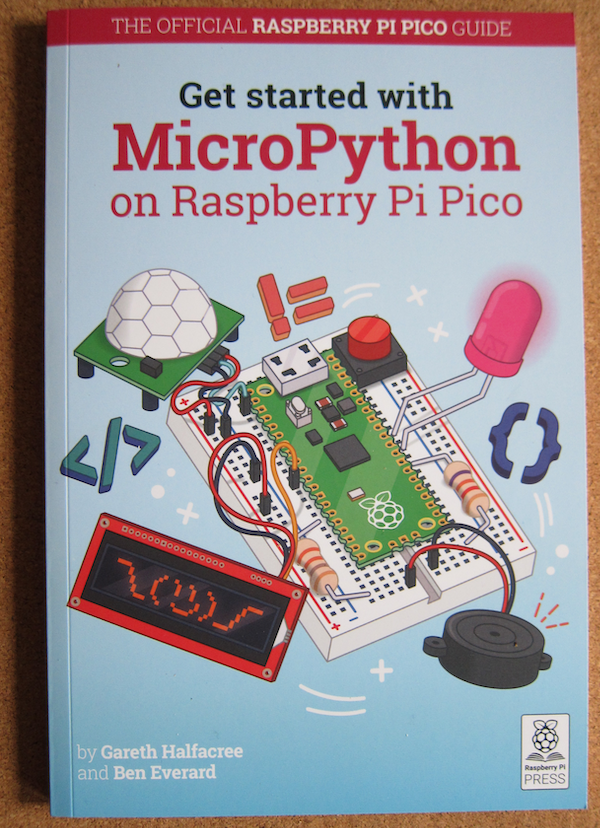
And if you want to program it in Micropython, Raspberry Pi Foundation has a book. It is available as a physical book or as a free PDF.


Sunday, 24 January 2021

Raspberry Pi Pico Microcontroller

 Raspberry Pi have just released a new product into a new market for them a low cost microcontroller. And not just a microcontroller using an existing piece of silicon, no, this is a in-house custom designed processor.

Why a microcontroller?

General purpose computers like the Raspberry Pi are great at doing lots of things, but that comes at a price. They can do lots of things that appear to humans  to be happening at the same time, but it is like juggling, if you are late getting to one of the items in the air, one or more of the items is going to come crashing down. By dedicating a microcontroller to the task, you can ensure the timely response.

Also, because microcontrollers do not have to contain all the clever hardware to handle lots of memory, task swapping and other things required for general purpose computers they are both economical in cost and energy requirements.

There are plenty of microcontrollers about such as the BBC Microbit and Arduino (and compatible), but most are built using an existing System On A Chip.

Raspberry Pi decided to build a dedicated microcontroller chip based on their experiences with the Sense Hat and the all in one Raspberry Pi 400.

What does Raspberry Pi Pico look like?


As you can see, it is much smaller than even the Raspberry Pi Zero (a WH example above). 

Out of the box it has only limited built in semsors and outputs, this is not a Circuit Playground Express.

Basically it has a green LED on GPIO pin 25 and a chip temperature sensor.

What is it for?

The Raspberry Pi Pico can be used where other microcontrollers would be used. It lacks the existing Arduino Shield eco-system, so generally where it is the basic I/O that is required.

It is small, and frugal with the power so it can run independently on two or three AA batteries.

How do you get one?

They are available from the usual suspects, I have one on order from Pimoroni.
In addition, they are on the cover of issue 39 of the print version of the Hackspace magazine.


What can you program it in?

At the moment there is a full C/C++ SDK and ports of Micropython and CircuitPython.
There is currently no Arduino implementation, but there will be an official RP2040 based Arduino device so I suspect that will not be a long wait.

Raspberry Pi RP2040

There is a full description of the RP2040 here, but these are the highlights:

  • In-house design using dual core ARM Cortex M0+
  • 264KB RAM
  • Upto 16MB of external Flash memory via a QSPI bus.
  • 30 GPIO pins (four owhich can be configured as analogue input)
  • Two each of UART, SPI and I2C controllers
  • 16 PWM channels
  • USB host and device support plus mass-storage boot mode for drag and drop programming
  • Eight Programmable I/O state machines

The eight PIO state machines are a particular innovation - they are programmable in a simple assembly language to perform tasks at set rates. Each instruction takes one cycle and is independent of the two main cores. This allows you to set up time sensitive operations at known speeds, irrespective of what the main processor is doing. Most microcontrollers would require bit-banging, using the processor to transmit or receive data by changing/reading the state of an input. The PIO allows this to be offloaded to a PIO with full control of the process. All the processor has to do is ensure that it is kept fed or emptied in time.

The chip is called an RP204 based on a naming system:

Cores: 2

CPU type: 0 ~ M0 - this is a loose description of the CPU type.

RAM: 4  = floor(log2(ram / 16k))

Flash: 0 = floor(log2(nonvolatile / 16k)) or zero in this case (the host board provides the Flash storage).

The Future

There are a range of products from Pimoroni, Adafruit, SparkFun and Arduino planned to use the RP2040, so we shall see.

References


Sunday, 5 July 2020

Reading USB (Serial) data

Most microcontrollers have an option to output data over the USB link.

It is helpful during development to be able to read state information and other values that allow the developer to see what is happening.

The first thing is to identify which USB port is in use.
            foreach (string port in ports)
            {
                Console.WriteLine(port);
            }
For my set up, COM5 was the one in use.
using (var sp = new System.IO.Ports.SerialPort("COM5", 115200, System.IO.Ports.Parity.None, 8, System.IO.Ports.StopBits.One))
            {
                Console.WriteLine("Reading serial port");
                sp.Open();
                while (true)
                {
                    var readData = sp.ReadLine();
                    Console.WriteLine($"[{readData}]");
                }
            }
This will display on the console anything output from the device.


Sunday, 14 June 2020

BBC Micro:Bit Menu system (with persistent choice)

The BBC Micro:Bit is a simple microcontroller with a 5 x 5 matrix of LEDs, two buttons, 3D magnetic and acceleration sensors and a CPU temperature sensor.
The two buttons can make complicated interfaces rather difficult, however it is possible to build one.
One aadditional feature of this menu system is that your choices are persistent. If you select menu item, power off the Micro:Bit then subsequently power it back one, it will remember the choice (subject to it not being reflashed of course).

Code

This was written in Micropython using the Mu editor.
from microbit import *
import os
import utime
menuitem = 0
if 'choice.opt' in os.listdir():
    with open('choice.opt') as choice:
        menuitem = int(choice.read())
display.scroll("Menu item" + str(menuitem))
start = utime.ticks_ms()+6000
interval = 2000
while True:
    now = utime.ticks_ms()
    if start > now or now - start > interval:
        if menuitem == 0:
            temp = temperature()
            interval = 2000
            display.scroll(str(temp) + 'C', delay=100, wait=False)
        elif menuitem == 1:
            temp = temperature()
            interval = 2000
            display.scroll(str(temp + 273.15) + 'K', delay=100, wait=False)
        elif menuitem == 2:
            level = display.read_light_level()
            interval = 2000
            display.scroll(str(level) + ' light', delay=100, wait=False)
        elif menuitem == 3:
            level = compass.get_field_strength()
            interval = 6000
            display.scroll(str(level) + ' nTesla', delay=100, wait=False)
        elif menuitem == 4:
            display.scroll("Menu test")
        start = now 
    if button_a.is_pressed():
        display.scroll("Menu", delay = 100)
        sleep(50)
        while not button_a.is_pressed():
            display.set_pixel(4,menuitem,5)
            if button_b.is_pressed():
                display.set_pixel(4,menuitem,0)
                menuitem = menuitem + 1
                if menuitem > 4:
                    menuitem = 0
                with open('choice.opt','w') as choice:
                    choice.write(str(menuitem))
                display.scroll("Menu item" + str(menuitem), delay = 100)
            sleep(100)
            display.set_pixel(4,menuitem,5)
            sleep(100) 
    sleep(400)
The persistent choice is handled by this code:
menuitem = 0
if 'choice.opt' in os.listdir():
    with open('choice.opt') as choice:
        menuitem = int(choice.read())
The menu item is given a default value (0).
The file 'choice.opt' is checked if it exists in the directory list, if it is, then the value of the menu item is read from the file and assigned to the menuitem variable. When a subsequent decision is made to change the menuitem, this value is written out to the file, making it available the next time the Micro:Bit is switched on.

The main loop is entered after the start variable is set in advance of the current tick count and the display interval is set (strictly speaking the interval should be dependent on the menu choice but it only affects the first cycle).

Each loop, if the difference between the ticks now and the (loop) start ticks is greater than the interval, then the menuitem is used to choose what to do.
In this example it is used to choose which sensor is read and the results displayed.
Menu choices are:

  1. Temperature in degrees Celsius.
  2. Temperature in Kelvin
  3. Light level (based on the light falling on the LED matrix)
  4. Magnetic field strength in nanoTesla (using the compass module)
  5. A message.
The first three keep the interval at two seconds, but the magnetic field strength is a longer piece of text, so that is stretched to six seconds by setting the interval.
The Start ticks value is set to the Now value.

The next part of the code checks for the A button (left side) being pressed.
If so, it then loops until the button is pressed again.
Inside that loop, pressing the B (right hand) button increments the menuitem value, writes it to the file and shows a pixel on the right hand column indication which option is currently chosen.
Pressing button A exits the loop and recommences the outer infinite loop.

Disadvantages

This does mean that during normal operation, button A is not available. This might not be an issue but is something to bear in mind.

References


Saturday, 13 June 2020

Pimoroni Envirobit

Pimoroni Envirobit


The Pimoroni Envirobit is a set of sensors for the BBC Micro:Bit .


As you can see, it is equipped with a slot to take the Micro:Bit, so no soldering is required.

The Envirobit is fitted with the following sensors:

  • BME280 environmental sensor - which measures temperature, pressure, humidity and can calculate the altitude based on a supplied base pressure level (discuss).
  • tcs3472 RGB sensor - which measures Red Green and Blue light levels as well as “white” light levels. Also includes two illuminating (white) LEDs,
  • Sound - a small microphone allows the sound level to be measured on one of the Micro:Bit’s analogue pins

Assembly

Assembly is simple. Take the Envirobit board with the sensors facing forward, and insert the Micro:Bit with the LEDs also facing forward.
Due to the nature of the connection, you can swap the Microbits if the colour scheme does not match your needs.

Software

The main software support for the Envirobit is orientated towards the Microsoft MakeCode block based system.
There is some support for MicroPython. There is a GitHub link here: https://github.com/pimoroni/micropython-envirobit

There are three python files in the Library.
  • sound.py
  • bme280.py
  • tcs3472.py

The files can be transferred to your Micro:Bit using the Files function in Mu.

Sound

Contrary to the description on GitHub, this is not a class, just three methods.

  • sound.read() - This takes a reading of the sound level and returns a value between 0 and 440. There is an offset value in the code to set the minimum sensitivity.
  • sound.wait_for_double_clap() - listen for two high level sound events in a second, returns True if detected
  • sound.wait_for_clap() - listen for a single high sound level event in a second, returns True if detected

tcs3472

This uses a class to access the TCS3472 sensor via I2C.
To use the sensor, import the module (having transferred it to the Micro:Bit) and instantiate an instance.
import tcs3472
light_sensor = tcs3472.tcs3472() 
Methods:

  • r, g, b = light_sensor.rgb() - returns a tuple of the corrected levels of red, green and blue out of 255
  • r, g, b = light_sensor.scaled() - return a tuple of the amounts of red, green and blue on a scale of 0-1
  • level = light_sensor.light() - return a raw reading of light level on a scale of 0-65535
  • light_sensor.set_leds(0) - Turn the LEDs off
  • light_sensor.set_leds(1) - Turn the LEDs on

BME280

This uses a class to access the BME280 sensor via I2C.
The instructions on GitHub are incorrect, there is a missing () on the end of the class instantiation. Python can be very unforgiving if you make a mistake of this kind.
import bme280
bme = bme280.bme280()

The bme280 class has the following methods:

  • temp = bme.temperature() - return the temperature in degrees C
  • pressure = bme.pressure() - return the pressure in hectopascals
  • humidity = bme.humidity() - return the relative humidity in %
  • alt = bme.altitude() - return the altitude in feet, calculated against the current QNH value
  • bme.set_qnh(value) - set the QNH value for calculating altitude

QNH is the atmospheric pressure adjusted to sea level (what the pressure sensor should read at sea level).
https://en.wikipedia.org/wiki/QNH

References

https://github.com/pimoroni/micropython-envirobit
https://en.wikipedia.org/wiki/QNH


Sunday, 8 July 2018

Programming the BBC micro:bit

One of the simplest methods of programming the micro:bit is using the web based MakeCode by Microsoft.

Here is an example of a "Hello World" program written using MakeCode.

This is the code generated as Javascript.

basic.forever(() => {
    basic.showString("Hello World!")
})

References

BBC micro:bit

The BBC micro:bit is a pocket sized programmable micro-controller designed for use in education.

As part of an education programme, these were given to schoolchildren to be used to teach the principles of programming. They were designed to be compact in size but have an assortment of sensors and feedback devices and to spark the creativity of children to the potential of programming.

After the first distribution, they were made available commercially for all to use.
The commercial version is supplied in a cardboard box containing the micro:bit, a small instruction manual and a safety guide. Minimum additional equipment is required, a USB to micro USB data cable (not a charging cable) and a computer (Windows/Mac/Linux) with a browser.
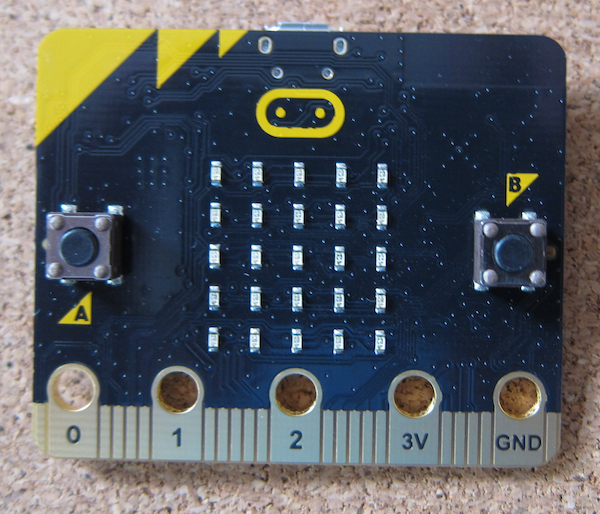
 The rear of the micro:bit, showing the labelling. As you can see it has a Bluetooth Low Energy aerial, magnetometer (compass), accelerometer, micro USB power and data socket, battery connector and processor. It also shows the connectors.
There are five big connectors suitable for crocodile clips, machine screws or conductive thread. On the front face they are labelled pins 0-2, 3V and Ground. Other pins are available through the edge connector. On this side is also the 5 x 5 LED display and two push buttons.

Reference


Sunday, 1 July 2018

GPS Stack - physical build

So this project is to build a simple GPS locator using an Arduino compatible controller, a LinkSprite GPS Shield and a LinkSprite LCD shield.

The specification for the Arduino allows the stacking of shields. What you do need to ensure is that there are no conflicts over pins.

 The controller is the Ciseco Xino RF board.
There is nothing overly important about using this rather than an Arduino UNO, except this board uses a mini USB socket for power so the DC in socket is the highest point.

The GPS shield fits on top. Aligning the pins is a bit worrying as they are a bit delicate and the LinkSprite assembly is a bit squint.
The topping on the stack is the LCD shield.
The alignment issues are clear on the sockets on the photograph above.

Here is the assembled stack.
The DC in socket contacts the


LinkSprite GPS Shield

The LinkSprite GPS shield provides GPS data for Arduino and compatible microcontrollers.
Another purchase from Maplin, this has not particularly good instructions. The photograph on the instructions page is unclear as to how to set up the shorting pins to select the serial port.

The shield takes an SD card, note that due to its advanced age, it only takes SD cards - not SDHC and above. It is a bit difficult to find 2GB cards.

References:

http://linksprite.com/wiki/index.php5?title=GPS_Shield_With_SD_Card_Slot_for_Arduino_V2.0_B

Ciseco Xino RF microcontroller

The Ciseco Xino RF is an Arduino Uno compatible microcontroller with a built in radio module.

Add caption
Maplins stocked the Raspberry Wireless Inventor Kit for the the original Raspberry Pi. It included a Xino RF micro and a matching radio card for the 26 pin connector on the original Raspberry Pi. There was a set in the Maplins closing down sale which was about the same price as an Arduino Uno (but with added LEDs etc) so I added it to my collection (I bought one with my original Model B).

The Xino RF can be used as an Arduino with the added advantage that it uses a Mini USB for power (the DC in port is the highest point on the board, unlike on the UNOs where the USB-A connector with a metal case is the highest point. There is a sketch available that will return it to the Wireless Inventors mode.

LinkSprite LCD Arduino Shield

The LinkSprite 16x2 LCD Shield is a display shield for Arduino compatible microcontrollers.

Maplins (late supplier of electronic bits) stocked a range of LinkSprite products. One of many problems was they had a lot of rather ancient stuff that sat on shelves and was more of interest to archaeologists. With the loss of Maplins, it can be difficult to identify the particular items, but LinkSprite does still have a products wiki here.

Do be aware that the pins used by this LCD shield do not match those on the Arduino examples sketches. To make it more confusing, the example code on the LinkSprite site works (by setting the values in the initialization call) but has not had the pin selection changed in the comments.

If you use the Arduino LCD Shield "HelloWorld" example code, you need to change the pins used :

  •  LCD RS pin to digital pin 8
  •  LCD Enable pin to digital pin 9
  •  LCD D4 pin to digital pin 4
  •  LCD D5 pin to digital pin 5
  •  LCD D6 pin to digital pin 6
  •  LCD D7 pin to digital pin 7
  •  Wiper to LCD VO pin (pin 3)

//const int rs = 12, en = 11, d4 = 5, d5 = 4, d6 = 3, d7 = 2;
const int rs = 8, en = 9, d4 = 4, d5 = 5, d6 = 6, d7 = 7; 

Ensure that the pins are not in use by any other shields or added hardware.

References:

https://www.arduino.cc/en/Reference/LiquidCrystal
http://linksprite.com/wiki/index.php5?title=16_X_2_LCD_Keypad_Shield_for_Arduino_V2
https://www.arduino.cc/en/Tutorial/HelloWorld