Saturday 15 December 2018

Raspbian Pixel desktop VNC Viewer

Since September 2016, all Raspberry Pi Raspbian distributions have included the RealVNC Virtual Network Computer server and viewer.

This allows the remote connection to the desktop on a Raspberry Pi machine. This is great if you want to to run your Raspberry Pi "headless" and do not want to use the Secure SHell (SSH).

You can connect to your Raspberry Pi from another (non Raspberry PI) machine by downloading and installing the RealVNC viewer (make your selection from the operating systems shown here https://www.realvnc.com/en/connect/download/viewer/. The RealVNC viewer is available from the Google Play Store (and probably from the Apple store as well). For Raspbian on the Raspberry Pi, wou can just get it from the Raspbian repository using the normal apt-get install (instructions are available from the above link)

Now I have an elderly Samsung Windows Netbook which is having a second life as a Raspbian Pixel netbook. Now this would be really useful to see what is happening on any live Raspberry Pis. Unfortunately, the non Raspberry PI distribution of Raspbian does not contain the RealVNC viewer.

So going back to the RealVNC downloads page, select the Linux option:
https://www.realvnc.com/en/connect/download/viewer/linux/

You need to select DEB x86 from the drop down menu, then click on Download VNC Viewer.

The file will (by default) appear in your Downloads directory. The one I received was called VNC-Viewer-6.18.907-Linux-x86.deb.

In the File Manager, right click and select Package Install. This will request your password to give the installer permission to make changes to the operating system (in the same way that normally you use SUDO to give heightened permissions).

Once it has been installed, the RealVNC viewer can be found in the Internet options on the start menu.

You will need to know either the ip address of the Raspberry Pi, or the network name. A default Raspberry Pi is normally called "raspberrypi", so should appear on the local network under the name "raspberrypi.home".

References:


Sunday 9 December 2018

PIMORONI Breakout Garden

The Pimoroni Breakout Garden HAT is a clever way of allowing the development of sophisticated sensor and display systems without having to do lots of soldering.

 As a HAT, it is fitted with a female 2x20 pin socket so it can be attached to any Raspberry Pi with 2x20 way expansion bus (Raspberry Pi Plus versions to date). Raspberry Pi Zero boards require the headers to be added (the Raspberry Pi Zero WH is supplied with the header already soldered/

This is going to be used with a Raspberry Pi Zero WH fitted into a Pibow Zero W case. To improve stability, a Pibow Breadboard Base was added to the bottom of the stack of laser cut acrylic slices that make up the case. The supplied bolts are long enough to take the additional slice.
Assembly was reasonably straightforward, I did need to ease a couple of the corners with a curved needle file to make the Zero board fit correctly.

To use a Zero with a keyboard and display, you do need to have an On The Go cable for the micro USB (top) and a Micro to HDMI adapter (bottom). I got mine as part of the Pimoroni OctoCam package.

The key feature of the Breakout Gatden HAT is the six large sockets on the top.

These are designed to take the special format breakout board from Pimoroni.

The first breakout board is the BME680 Air Quality Sensor.
Back
The front shows the five connectors. The power and ground connections are diode protected, so if you do plug them in the wrong way round, nothing bad (or indeed nothing at all) happens.

The breakout has temperature, pressure, humidity and air quality sensors built in.

The LSM303D is a combined accelerometer and magnetometer


It can provide X, Y, Z values for acceleration and magnetic field strength (making it suitable for use as a digital compass).

The third sensor is the BMP280 temperature, pressure and altitude sensor.

The last breakout board I have is the 1.12" 128x128 pixel OLED display board.


Next, putting them all to work.

Friday 23 November 2018

FutureLearn Begin Programming Week 3 Android game video

This is for the Week 3 element of the FutureLearn course Begin Programming.

Because I am not very good with video games, I have left the one point for hitting the ball, and five points for hitting the target.

This was recorded with the emulator's built in screen recorder, hence the odd resolution. 

Thursday 22 November 2018

Android SDK, Emulator and the Intel HAXM

Android SDK and the Intel HAXM

The Android SDK has an Android emulator that can emulate ARM and x86 based Android devices.
The build #AI-181.5540.7.32.5056338, built on October 9, 2018 dated October 2018 has an issue with ARM based emulation which prevents it from working.
The x86 emulation requires the availability of the Intel Hardware Accelerated Execution Manager.

This process will require you to go into the BIOS and make changes. It is possible to seriously break your computer if you make the wrong changes.

The Hardware Accelerated Execution Manager can be downloaded via the Android Studio SDK manager. It will say it has installed it, but it hides some installation issues.
Once you have "installed" it, on a Windows PC go to:
C:\Users\<user>\AppData\Local\Android\Sdk\extras\intel\Hardware_Accelerated_Execution_Manager

First you need to check that your hardware is suitable to run HAXM.
Start a command prompt (type cmd in the search box).
Copy the file path from File Explorer and in the command prompt type CD .
Then paste the file path and press return.
Type dir and return.

The command window will show something similar to this:
22/11/2018  16:37    <DIR>          .
22/11/2018  16:37    <DIR>          ..
30/10/2018  16:47           108,792 haxm_check.exe
22/11/2018  16:38               225 haxm_silent_run.log
30/10/2018  16:47         2,937,888 intelhaxm-android.exe
30/10/2018  16:47             2,907 package.xml
30/10/2018  16:47             4,483 Release Notes.txt
30/10/2018  16:47             8,675 silent_install.bat
30/10/2018  16:47             2,274 silent_install_readme.txt
               7 File(s)      3,065,244 bytes
Type haxm_check.exe and return.
Hopefully the response will be:
VT support - yes
NX support - yes
If it is, then you can proceed. If not, you will have to wait for the ARM emulator to be fixed.
If you run the intelhaxm-android.exe program (right click and run as administrator) it will probably tell you it is installed.

What you need to do is uninstall it (close Android Studio if it is open).

Once it has been uninstalled, run intelhaxm-android.exe again and install it. It will probably tell you that the VT support is not enabled and roll back the installation. If it works, well done - nothing more to do.

To enable the VT support, you need to go into your computer’s BIOS or equivalent.

You will need to know how to get into the BIOS, this normally requires the machine to be restarted and then various buttons pressed.

It is a good idea to find out the access method before shutting your computer down.

HP laptops post 2011 generally require the Escape key to be repeatedly pressed after starting. From there follow the instructions.

Close everything down and shut down your computer.

Enact the arcane gestures required and go into the BIOS manager. Enable the VT (Virtualisation technology). Save and restart the machine.

Once you are logged in, go back to C:\Users\<user>\AppData\Local\Android\Sdk\extras\intel\Hardware_Accelerated_Execution_Manager
And run the intelhaxm-android.exe program as administrator.


This should allow you to set up an X86 emulator in the Android Studio and start it.

Friday 9 November 2018

SQL delimited string to table function

Sometimes data suppliers do not make their data easy to separate. Other times you might want to split some other data up.

This SQL Table function will take a string comprising a list of substrings with a specified specified delimiter and returns a table containing the substrings

-- =============================================
-- Author: Technology Is Not Dull
-- Create date: 19/01/2016
-- Description: Takes a delimited string list and returns a table
-- =============================================
CREATE FUNCTION [dbo].[stringToTable]
(
@string VARCHAR(200),
@delimiter char(1)
)
RETURNS
@rettable TABLE
(
stringbit varchar(50)
)
AS
BEGIN
--***# select * from dbo.stringToTable(POLYETHYLENE GLYCOL 3350; POTASSIUM CHLORIDE; SODIUM BICARBONATE; SODIUM CHLORIDE; SODIUM SULFATE ANHYDROUS',';')
DECLARE @start INT, @end INT
    SELECT @start = 1, @end = CHARINDEX(@delimiter, @string)
    WHILE @start < LEN(@string) + 1 BEGIN
        IF @end = 0
            SET @end = LEN(@string) + 1
     
        INSERT INTO @rettable (stringbit)
                  VALUES(SUBSTRING(@string, @start, @end - @start))
        SET @start = @end + 1
        SET @end = CHARINDEX(@delimiter, @string, @start)
     
    END
    RETURN
END
GO

Tuesday 6 November 2018

Circuitverse - online digital logic simulator

Circuitverse is a free online digital logic simulator developed by students at IIIT Bangalore.

It allows the building of digital logic systems in the comfort of your own browser.

The user can select various input and output devices plus logic gates, wire them up and then test them.

The circuits can be saved, and images of the circuits produced. The circuits can be Public, which allows them to shared, useful for distance learning.

Previously saved circuits can be retrieved, but you need to click on the user name to get to the menu with the "My Circuits" option.

The developers say that though you could undertake a full CPU implementation, it is really designed for educational work.

It is certainly an interesting piece of software, and is happy running on a Raspberry Pi 3.

Monday 5 November 2018

Circuitverse - image for something else

Circuitverse.org is an an online digital logic simulator that allows you to build digital circuits in your browser.

I will be coming back to this later, but I needed somewhere to host an image.
There are two circuits, the top right one is showing a plain NAND gate, the bottom one builds an OR gate from three NAND gates.

This is for the FutureLearn How Computers Work course, from the Raspberry Pi Foundation.

Monday 22 October 2018

Browser size - Javascript

Sometimes when you are building a web page it is useful to know what the browser size is, so you check it will display correctly if it is on a desk top, lap top, tablet or mobile.

The following Javascript will put the browser client size as the title.
<html>
<head>
    <script>
        function titleIsSize() {
            document.title = "" + document.body.clientWidth + " pixels.";           
        }
    </script>
</head>
<body  onresize="titleIsSize()"  >
</body>
</html>

Monday 15 October 2018

Raspberry Pi sound not working on HDMI

By default the Raspberry Pi will channel sound through the HDMI connection to a suitable television/monitor.

Most of the time that will work automatically (if it thinks the television/monitor is not equipped with a speaker or speakers, it routes it through the headphone socket).

The key thing is the "sometime".

Some television/monitors do not appear to tell the Raspberry Pi they have a speaker. This may be due to the monitor, or due to the HDMI cable in use.

The easiest way of forcing the sound to be output via one of the channels is to right click on the loudspeaker icon. The drop down will show available audio output devices, the tick indicating the selected one. Make your choice there.

You can also use the command line:
amixer cset numid=3 2

The parameter 2 sets output to HDMI, 1 sets it to the headphone socket and 0 sets it to default.

It is also possible using the configuration screen and by editing the /boot/config.txt file. See the reference for details.

References:
https://www.raspberrypi.org/documentation/configuration/audio-config.md

Wednesday 19 September 2018

CircuitPython: writing to the file system.

Circuitpython has a very easy way of uploading code and data to the microcontroller, the microcontroller's storage appears as a USB storage device on the host's operating system. To move code and data to the microcontroller, you simply copy everything to the volume.

Unfortunately this does mean that, by default, Circuitpython cannot write data to its own storage (it is read only) and so it cannot write data that will visible to the host.

However it is possible to change that in the optional boot.py code file.

The boot.py file is only run on the first boot of the device (power up) and not when REPL is restarted or when you save a file. The microcontroller needs to be Ejected as a USB device and the reset button pressed.

Note: When you change it from read only, it is not possible to update the code on the microcontroller - including the boot.py.

The boot.py file needs to contain the following code:
import storage
storage.remount("/", False)

The first line imports the storage module, allowing access to OS functions.
The second line remounts the storage with readonly set to false.

The boot.py file can be "removed" via REPL (Read - Evaluate - Print - Loop). This is very like a command line interface combined with an (xPython) interpretor.

To access REPL on Mu:
Click on the Serial button on the ribbon. This will open a serial connection to the connected microcontroller.
Press CTRL-C (keyboard interrupt) to stop CircuitPython from continuing with whatever it is doing.
Press any key (as instructed).
Use the REPL.

To remove the boot.py, you need to rename the file via REPL:
import os
os.listdir("/")
os.rename("/boot.py", "/boot.bak")

The first line imports the storage module, allowing access to OS functions.
The second lists the contents of the root of the microcontoller's storage.
The third renames the boot.py file to boot.bak.

The microcontroller needs to be ejected (as a USB device) and the reset button pressed (physically unplugging it after ejecting it will also work).

References

https://codewith.mu/en/tutorials/1.0/repl
https://learn.adafruit.com/cpu-temperature-logging-with-circuit-python/writing-to-the-filesystem
https://circuitpython.readthedocs.io/en/2.x/shared-bindings/storage/__init__.html

MU Python, Micropython and CircuitPython editor

The Micro:bit can be programmed offline using the Mu editor. Until recently the editor available on the Raspbian repository has been an earlier version without support for the Radio module.

For a Raspberry Pi, Mu is now included in the Recommended Software option.

Instructions for installation are listed in the references.

References:

https://codewith.mu/
https://www.raspberrypi.org/blog/mu-python-ide/
https://projects.raspberrypi.org/en/projects/getting-started-with-mu

Monday 13 August 2018

Future Learn

FutureLearn is a Massive Open Online Course Platform. The courses are developed by partner organisations and can be studied using a mobile or tablet computer (although some courses may require additional technology - such as a piano for the Jazz Piano course).

FutureLearn was created by The Open University and (originally) twelve partner universities to provide on-line courses. Over the five plus years it has been in existence, the partners count has increased to 141.

The courses cover a wide area of study, technology, medicine, anthropology, marketing, arts, humanities, languages, music etc.

The courses are free, but access is for a limited amount of time. To extend access indefinitely and to receive a certificate of study requires a payment. A number of the courses are modules from a larger course including degree courses.

References:


Thursday 12 July 2018

Plotting temperature over time on a Raspberry Pi

A while back I assembled a temperature measuring system using a DS18B20 temperature sensor which was read by an Arduino fitted with an Ethernet Shield.


To record the temperature over time, I wrote a simple Python program running on a Raspberry Pi 3 to access the Arduino over my local network.

It was not the most elegant of programs, but it recorded the time and temperature into a CSV file.

The CSV file was then opened in Libre Calc, and the results plotted out.


Sunday 8 July 2018

Programming the BBC micro:bit

One of the simplest methods of programming the micro:bit is using the web based MakeCode by Microsoft.

Here is an example of a "Hello World" program written using MakeCode.

This is the code generated as Javascript.

basic.forever(() => {
    basic.showString("Hello World!")
})

References

BBC micro:bit

The BBC micro:bit is a pocket sized programmable micro-controller designed for use in education.

As part of an education programme, these were given to schoolchildren to be used to teach the principles of programming. They were designed to be compact in size but have an assortment of sensors and feedback devices and to spark the creativity of children to the potential of programming.

After the first distribution, they were made available commercially for all to use.
The commercial version is supplied in a cardboard box containing the micro:bit, a small instruction manual and a safety guide. Minimum additional equipment is required, a USB to micro USB data cable (not a charging cable) and a computer (Windows/Mac/Linux) with a browser.
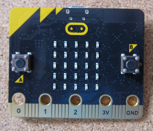
 The rear of the micro:bit, showing the labelling. As you can see it has a Bluetooth Low Energy aerial, magnetometer (compass), accelerometer, micro USB power and data socket, battery connector and processor. It also shows the connectors.
There are five big connectors suitable for crocodile clips, machine screws or conductive thread. On the front face they are labelled pins 0-2, 3V and Ground. Other pins are available through the edge connector. On this side is also the 5 x 5 LED display and two push buttons.

Reference


Use of 32GB+ SD/micro SD cards with the Raspberry Pi

Introduction

The SD and micro SD card are now nearly ubiquitous. Every year the size and speed improve (while the cost only fluctuates).
I use a GoPro camera that takes SD cards, and have recently started to use 64GB cards as that means that I only have to worry about battery life and not running out of storage.
My desktop computer happily reads the cards and allows me to view the photographs and video. While I am away, I take a Raspberry Pi as an entertainment system and to back up my videos. I discovered that my new 64GB card was not visible to the Pi.

SDXC cards (greater than 32GB capacity)

SDXC (Secure Digital eXtended Capacity) extended the capacity of SD format cards beyond the 32GB limit of the previous SDHC (Secure Digital High Capacity) standard. However, they are supplied and assumed to use the proprietary exFAT file system.
Some card readers will always assume that the card will be exFAT format and will treat any other format as defective. This can lead to data loss

Raspberry Pi reading exFAT SDXC cards

Out of the box the Raspbian cannot read SDXC cards formatted with the exFAT filesystem. Due to the patented technologies inherent in any implementation of exFAT, it is not possible to include solutions capable of implementing exFAT in Linux.
However there are solutions within the official repository for Raspbian (and most other Linux distributions).
At the command line or open a terminal window and use the following
Sudo apt-get install exfat-fuse exfat-utils
Restart and you will be able to read your SDXC card and look at the photographs from your camera.

Booting from a 32GB+ SD/Micro SD card

The Raspberry Pi Bootloader can only read FAT and FAT32 cards, and as noted above 64GB and above cards are supplied with the exFAT format.
To use a 64GB card as a boot card it needs to be formatted to FAT32.
The built in disc formatting tools on Linux and MACOS are quite capable of formatting the cards. Make sure to select the FAT32 format.
The case with Windows is slightly different, a third party producr will need to be used as the Windows disc formatter will only format cards greater thn 32GB to exFAT.


References

https://en.wikipedia.org/wiki/Secure_Digital#SDXC
https://en.wikipedia.org/wiki/ExFAT
https://en.wikipedia.org/wiki/ExFAT#Reimplementations
https://www.raspberrypi.org/documentation/installation/sdxc_formatting.md

Tuesday 3 July 2018

The Sketch That Does Nothing

One of the joys of playing with Arduinos is putting something together, and then taking it apart and building something else.

The various shields sometimes make use of the same pins, and the result of using the previous sketch might be unpredictable.

This sketch literally does nothing, except tell you it does nothing over the serial link.

void setup() {
  // Technology Is Not Dull 2018
  // Use this project to clear sketch from Arduino Board 
  // before fitting a shield so the starting sketch does not 
  // cause any issues with the newly fitted shield.
    Serial.begin(9600);   
    Serial.println("Starting The Project That Does Nothing!");    
    Serial.println("Closing Serial port");
    Serial.end();
}

void loop() {
  // Nothing to see, move along...

}

Sunday 1 July 2018

GPS Stack - physical build

So this project is to build a simple GPS locator using an Arduino compatible controller, a LinkSprite GPS Shield and a LinkSprite LCD shield.

The specification for the Arduino allows the stacking of shields. What you do need to ensure is that there are no conflicts over pins.

 The controller is the Ciseco Xino RF board.
There is nothing overly important about using this rather than an Arduino UNO, except this board uses a mini USB socket for power so the DC in socket is the highest point.

The GPS shield fits on top. Aligning the pins is a bit worrying as they are a bit delicate and the LinkSprite assembly is a bit squint.
The topping on the stack is the LCD shield.
The alignment issues are clear on the sockets on the photograph above.

Here is the assembled stack.
The DC in socket contacts the


LinkSprite GPS Shield

The LinkSprite GPS shield provides GPS data for Arduino and compatible microcontrollers.
Another purchase from Maplin, this has not particularly good instructions. The photograph on the instructions page is unclear as to how to set up the shorting pins to select the serial port.

The shield takes an SD card, note that due to its advanced age, it only takes SD cards - not SDHC and above. It is a bit difficult to find 2GB cards.

References:

http://linksprite.com/wiki/index.php5?title=GPS_Shield_With_SD_Card_Slot_for_Arduino_V2.0_B

Ciseco Xino RF microcontroller

The Ciseco Xino RF is an Arduino Uno compatible microcontroller with a built in radio module.

Add caption
Maplins stocked the Raspberry Wireless Inventor Kit for the the original Raspberry Pi. It included a Xino RF micro and a matching radio card for the 26 pin connector on the original Raspberry Pi. There was a set in the Maplins closing down sale which was about the same price as an Arduino Uno (but with added LEDs etc) so I added it to my collection (I bought one with my original Model B).

The Xino RF can be used as an Arduino with the added advantage that it uses a Mini USB for power (the DC in port is the highest point on the board, unlike on the UNOs where the USB-A connector with a metal case is the highest point. There is a sketch available that will return it to the Wireless Inventors mode.

LinkSprite LCD Arduino Shield

The LinkSprite 16x2 LCD Shield is a display shield for Arduino compatible microcontrollers.

Maplins (late supplier of electronic bits) stocked a range of LinkSprite products. One of many problems was they had a lot of rather ancient stuff that sat on shelves and was more of interest to archaeologists. With the loss of Maplins, it can be difficult to identify the particular items, but LinkSprite does still have a products wiki here.

Do be aware that the pins used by this LCD shield do not match those on the Arduino examples sketches. To make it more confusing, the example code on the LinkSprite site works (by setting the values in the initialization call) but has not had the pin selection changed in the comments.

If you use the Arduino LCD Shield "HelloWorld" example code, you need to change the pins used :

  •  LCD RS pin to digital pin 8
  •  LCD Enable pin to digital pin 9
  •  LCD D4 pin to digital pin 4
  •  LCD D5 pin to digital pin 5
  •  LCD D6 pin to digital pin 6
  •  LCD D7 pin to digital pin 7
  •  Wiper to LCD VO pin (pin 3)

//const int rs = 12, en = 11, d4 = 5, d5 = 4, d6 = 3, d7 = 2;
const int rs = 8, en = 9, d4 = 4, d5 = 5, d6 = 6, d7 = 7; 

Ensure that the pins are not in use by any other shields or added hardware.

References:

https://www.arduino.cc/en/Reference/LiquidCrystal
http://linksprite.com/wiki/index.php5?title=16_X_2_LCD_Keypad_Shield_for_Arduino_V2
https://www.arduino.cc/en/Tutorial/HelloWorld

Arduino Installation on the Raspberry Pi

Though most software is available on the Raspberry Pi through the use of the APT repository, for some reason the version of the Arduino IDE is rather old, and possibly non standard.

To obtain the latest version you need to grab it from the Arduino web site here.

Follow the instructions and remember to choose the com port.

Wednesday 27 June 2018

UBUNTU update after end of life - a tale of Zesty Zapu (17.04) to Bionic Beaver (18.04)

Background

A long (in computer terms) while ago I bought an Intel NUC as my first venture into building a computer from scratch (not exactly challenging - I only had to install the memory and the hard drive and then boot it off of an Ubuntu Live USB).

It is not particularly fast (still faster than any of my Raspberry Pis), but it is useful for some tasks (amongst others it runs Inkscape and does not get tied in a knot when logging into YouTube). It gets hauled out occasionally when I need it.

I dutifully update the operating system (starting with 14.04 Trusty Tahr). Now Trusty Tahr is a Long Term Support release but this is not a production machine so with each release version I updated it to the latest stable version.

And then I did not use it for a while.

I recently needed to upload something to YouTube, and once completed I went to update the operating system...

At which point the updater could not find the repository as Zesty Zapus was retired on the 13th of January 2018.

First point of call was a Google search for information. This brought me to reference 1. This was informative, but did assume that the Aptitude package was already installed.

A further Google brought me to Reference 2 for a simpler command line method.

Upgrade method

Please ensure you have backed up the machine before upgrading. 
These instructions are supplied "as is" and with no guarantees. 
Please use them in conjunction with the references and common sense.
So here is my version, based on the two references and my experience (please read the referenced pages for more detail).
First the sources.list file needs to be edited - my installation was fairly vanilla so had no strange sources.
Either copy the existing file or comment out the existing entries.
Command line:
sudo nano /etc/apt/sources.list
Replace with the following lines (replace the "zesty" with your version if that is different):

## EOL upgrade sources.list 
# Required 
deb http://old-releases.ubuntu.com/ubuntu/ zesty main restricted universe multiverse 
deb http://old-releases.ubuntu.com/ubuntu/ zesty-updates main restricted universe multiverse 
deb http://old-releases.ubuntu.com/ubuntu/ zesty-security main restricted universe multiverse

The next stage is to run the apt update command to obtain the last version information (using the new repositories):

sudo apt update

Once that has completed the versions of the software needs to be upgraded.

sudo apt upgrade

This will take some time.

Once this has completed you need to run the distribution upgrade.

sudo apt dist-upgrade
If this does not work (reporting no suitable upgrades), restart the computer.

Once it has completed you need to restart the computer again.

After you have logged in again, you run the release upgrade. This will take a long time, hours.

sudo do-release-upgrade

Once that completes you will have an installation of Artful Aardvark (17.10). This is only supported until July 2018 so you will need to upgrade it to Bionic Beaver.

This should be automatic, except you have slightly messed up the settings by editing the sources.list file.

Bring up the settings panel and select the updates pane. Select the sources by clicking in the tick boxes. It will then ask you if you want to check if there are updates. If it does not, try swapping the check interval (never to daily seems to work).

You can then follow the instructions for the upgrade to Bionic Beaver.

References:

https://help.ubuntu.com/community/EOLUpgrades
https://ubuntuforums.org/showthread.php?t=2382832
https://en.wikipedia.org/wiki/Ubuntu_(operating_system)#Releases

Tuesday 13 March 2018

In The Beginning There Was... the ZX81

My first computer was a Sinclair Research ZX81.
I thought that would make a good first post.

My ZX81 only had a brief but busy time as my only computer. When I received it for my birthday, it had a massive 1024 bytes of RAM. The memory was shared between display, the operating system and the user programs. The display dynamically occupied memory, so as you increased the number of displayed lines it occupied more memory.

For Christmas I got the 16K RAM pack (sitting on top of the manual). This occupied the same mempry map as the on-board memory (you did not end up with 17K of memory).

One of the cost cutting measures of the design was the membrane keyboard. It was not particularly good and so there was a number of companies supplying better quality keyboard. The one above is from Redditch Electronics. To install it you had to open the case and pass the two ribbon cables through and replace the ribbon cables from the existing keyboard. This is similar to fitting a camera to the Raspberry Pi, but without all the supporting videos found on the Internet.

The other box is a sound card. The ZX81 expansion port allowed the addition of a number of devices, with the RAM pack as the last item. Using the AY8192 sound chip, it allowed the programmed generation of sounds. Certain games would also also make use of the sound generation.

Not shown is the cassette player used for storage. Not the most reliable of storage media.

I do seem to have misplaced the power supply. It may be in the box with the ZX-Spectrum, its successor.