Showing posts with label Breakout Garden. Show all posts

Sunday, 20 February 2022

PICO Breakout Garden Base

The Pimoroni PICO Breakout Garden Base has a socket for a Raspberry Pi PICO (available from Pimoroni with headers pre-soldered) plus four I2C sockets and two SPI sockets compatible with the Pimoroni breakout garden breakouts. Pimoroni also do a Breakout Garden to QT/QWIIC adapter.


This allows soldering free development (assuming you buy the PICO with headers attached) and reuse of the various breakouts (with other PICOs including the Explorer Base or Raspberry Pis).

There are libraries for C++, MicroPython and Circuit Python.

Installation

Hardware

Breakout Garden Base, self adhesive feet and a Raspberry Pi PICO.
The printed paws on the underside show where the self adhesive feet go.


Before fitting the Raspberry Pi PICO to the Breakout Garden Base, I would recommend testing the PICO. The Blink program (that flashes the PICO's built in LED) is a good test.

The Breakout Garden Base has two rows of sockets to take the pins soldered to the Raspberry Pi PICO microcontroller. Match the orientation of the Pico with the drawing between the sockets and align the pins on the Raspberry Pi PICO with the holes in the sockets and gently and evenly apply pressure until the PICO is in place.

Software

To use the I2C and SPI sockets on the base, Pimoroni have created a custom UF2 file including the required drivers. Follow the instructions here: https://learn.pimoroni.com/tutorial/hel/getting-started-with-pico

If you find the latest Pimoroni UF2 version does not work as expected, use the Update Firmware option on Thonny to return to a vanilla flavour UF2 and reload the Blink example.

It might be that the latest version has introduced a bug in the Breakout Garden handling. Download and install an earlier version of the Pimoroni UF2.

It is very useful to add parts of the Blink example to your code when testing to show that the code is working.

There are examples for a number of the breakouts available.
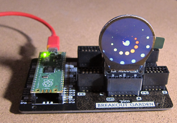
1.3" SPI Colour Round LCD example in operation.

References

https://shop.pimoroni.com/products/pico-breakout-garden-base

https://shop.pimoroni.com/products/raspberry-pi-pico?variant=32402092326995

https://shop.pimoroni.com/collections/breakout-garden

https://shop.pimoroni.com/products/breakout-garden-to-qwiic-adaptor

https://en.wikipedia.org/wiki/I%C2%B2C

https://en.wikipedia.org/wiki/Serial_Peripheral_Interface

https://learn.pimoroni.com/tutorial/hel/getting-started-with-pico

https://github.com/pimoroni/pimoroni-pico/releases

https://github.com/pimoroni/pimoroni-pico/tree/main/micropython/examples


Monday, 17 January 2022

Raspberry Pi Pico Explorer

The Raspberry Pi Pico Explorer is a plug-in board that provides a number of built-in devices including a 240x240 colour display, four buttons, a piezo buzzer, two I2S Breakout Garden sockets and sockets connected to the Pico's pins plus a small solderless breadboard.

A Raspberry Pi Pico with pre-soldered headers makes development easy without needing to solder delicate electronics.


Assembly was easy, care being taken to make sure all the pins aligned with the corresponding holes in the socket on the board.

Updating the Firmware

To use the components on the Explorer board, Pimoroni has created a custom UF2 file, including the required drivers. As of 03/01/2022 the latest version of the Pimoroni firmware (0.3.2) does not work, use version 0.3.1. This might not be the case for other boards.

Use the Update Firmware option on Thonny to return to a vanilla flavour and the Blink example if the current Pimoroni version does not work as expected. Select an earlier version of the UF2 and try again.

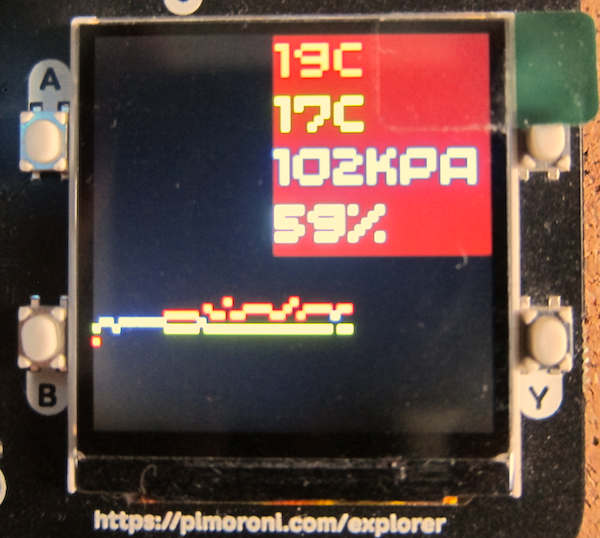
There is an example that measures the cpu temperature which is then displayed as text and a bar graph.
The next stage was to make use of the Breakout Garden sockets and add some breakout units. 
To provide some measurements, a BME680 environmental sensor was added to the right hand socket. In the left hand socket is a rotary encoder with a built in RGB LED.
The two sockets allow the addition of two breakouts. PIMORONI have a range of breakouts, including additional convertors that allow connection to STEMMA or Qwiic devices.

The BME680 breakout is an older model, the current version includes a built in STEMMA or Qwiic connector.
The example program was modified to get the temperature, pressure and humidity from the BME680 sensor plus the cpi temperature.

The code to set the encoder's RGB LED colour was also added.
The graph code was designed to display both the cpu temperature and the sensor temperature.

Finally a maximum and minimum sensor temperature was added to the display.

Code

Do check the indenting as Python uses the indenting to define the structure of the program.

import machine
import utime

from breakout_bme68x import BreakoutBME68X
from pimoroni_i2c import PimoroniI2C

PINS_BREAKOUT_GARDEN = {"sda": 4, "scl": 5}
PINS_PICO_EXPLORER = {"sda": 20, "scl": 21}

i2c = PimoroniI2C(**PINS_PICO_EXPLORER)

# Pico Explorer boilerplate
import picoexplorer as display
width = display.get_width()
height = display.get_height()
display_buffer = bytearray(width * height * 2)
display.init(display_buffer)

# BME68x configuration
bme = BreakoutBME68X(i2c)
#bme.configure(FILTER_COEFF_3, STANDBY_TIME_1000_MS, OVERSAMPLING_16X, OVERSAMPLING_2X, OVERSAMPLING_1X)

# reads from Pico's temp sensor and converts it into a more manageable number
sensor_temp = machine.ADC(4)
conversion_factor = 3.3 / (65535)

# Set up text areas
blockHeight = 33
textBlocks = 8
textArea=list()
for x in range(textBlocks):
    if(textBlocks>4):
        if(x<4):
            textArea.append([10,(blockHeight*x)+1,120,blockHeight])        
        else:
            textArea.append([120,(blockHeight*(x-4))+1,120,blockHeight])
    else:
        textArea.append([120,(blockHeight*x)+1,120,blockHeight])

# Set up background and text pens
background_pen = display.create_pen(0,0,0)
cpu_temp_pen = display.create_pen(255, 64, 64)
bme_temp_pen = display.create_pen(64, 255, 64)
pressure_pen = display.create_pen(64, 64, 255)
humidity_pen = display.create_pen(0, 255, 255)

# Define number of pixels for the graph points
graph_element_size = 1
graph_y_scale = 4

def drawTemp(i,cpu_temp,sensor_temp):
    diff = abs((cpu_temp*graph_element_size)-(sensor_temp*graph_element_size))
    if(diff<graph_element_size):
        display.set_pen(255,255,0)
        display.rectangle(i, height - (cpu_temp * graph_y_scale), graph_element_size,graph_element_size)
    else:
        display.set_pen(cpu_temp_pen)
        display.rectangle(i, height - (cpu_temp * graph_y_scale), graph_element_size,graph_element_size)
        display.set_pen(bme_temp_pen)
        display.rectangle(i, height - (int(sensor_temp) * graph_y_scale), graph_element_size,graph_element_size)
    
def writeInBlock(text, location, pen, paper, size):
    # Draw background to clear display area
    display.set_pen(paper)
    display.rectangle(location[0],location[1],location[2],location[3])
    # Write text in location one pixel left and down
    display.set_pen(pen)
    display.text(text, location[0]+1,location[1]+1,100,size)
    
# Initialise run variables
i = 0
count = 0
max_temp = 0
min_temp = 100

while True:
    # the following two lines do some maths to convert the number from the temp sensor into celsius
    reading = sensor_temp.read_u16() * conversion_factor
    temperature = round(27 - (reading - 0.706) / 0.001721)
    bmetemp, pressure, humidity, gas_resistance, status, gas_index, meas_index = bme.read()
    max_temp=max(max_temp,bmetemp)
    min_temp=min(min_temp,bmetemp)
    
    # Clear the display and reset counter if the graph reaches the right hand side
    if i >= (width + 1):
        i = 0
        display.set_pen(0, 0, 0)
        display.clear()

    # Draw graph element
    drawTemp(i,temperature,bmetemp)

    writeInBlock("{:.0f}".format(temperature) + "c", textArea[0],cpu_temp_pen,background_pen,4)
    writeInBlock("{:.0f}".format(bmetemp) + "c", textArea[1],bme_temp_pen,background_pen,4)
    writeInBlock("{:.0f}".format(pressure/1000) + "kPa", textArea[2],pressure_pen,background_pen,3)
    writeInBlock("{:.0f}".format(humidity)+"%", textArea[3],humidity_pen,background_pen,4)
    writeInBlock("Mx {:.0f}".format(max_temp) + "c", textArea[4],bme_temp_pen,background_pen,3)
    writeInBlock("Mn {:.0f}".format(min_temp) + "c", textArea[5],bme_temp_pen,background_pen,3)
    # time to update the display
    display.update()

    # waits for 5 seconds
    utime.sleep(1)

    # Set next graph element location
    i+=graph_element_size


Saturday, 26 June 2021

Temperature measuring Web Server

So, having had the Pimoroni Breakout Garden for a while and having used it as a temperature measurement device with a BME680 and display, I needed to measure the temperature and compare it with the temperature measured  by the analogue sensor of an Adafruit PyPortal and the CPU temperature.

The BME680 results are affected by the heat generated by the CPU, and a correction formula based on the CPU temperature was used to compensate for the CPU temperature.

An alternative is to separate the temperature sensor from the CPU.

This was achieved using a Breakout Garden to Stemma QT/QWIIC adapter and STEMMA QT / Qwiic to Breakout Garden Adapter  joined by a JST to JST cable. A BMP280 breakout was plugged in at one end, and the other plugged into the Breakout Garden. This should provide sufficient thermal isolation from the hot CPU.


Software installation

The Python library for the BMP280 temperature, pressure and altitude sensor is available via PIP. As with all installations, check if pip is for the now obsolete Python 2.x or Python 3.x. If the former, then use pip3 (that is the case on my Raspberry Pi Zero development systerm).

sudo pip3 install bmp280

The easiest way to make the data available to an Internet connectable device is by making the temperature measuring Raspberry Pi a web server.

The Flask library is similarly installed with pip. Note Flask starts with a capital letter
sudo pip3 install -U Flask

Web Server

This is a very simple web server, it has two  pages - /temperature and /json.

from flask import Flask, render_template
import time
import datetime
import json
from bmp280 import BMP280

try:
    from smbus2 import SMBus
except ImportError:
    from smbus import SMBus
app = Flask(__name__)

@app.route('/temperature')
def temperature():
    now = datetime.datetime.now()
    timeString = now.strftime("%Y-%m-%d %H:%M")
    temperature = bmp280.get_temperature()
    temp = '{:05.2f}*C'.format(temperature)
    templateData = {
      'temperature' : temp,
      'time': timeString
      }
    return render_template('temperature.html', **templateData)

@app.route('/json')
def tempjson():
    now = datetime.datetime.now()
    timeString = now.strftime("%Y-%m-%d %H:%M")
    temperature = bmp280.get_temperature()
    temp = '{:05.2f}'.format(temperature)
    templateData = {
      'temperature' : temp,
      'time': timeString
      }

    return json.dumps(templateData)

if __name__ == '__main__':
    bus = SMBus(1)
    bmp280 = BMP280(i2c_dev=bus)
    app.run(debug=True, host='0.0.0.0')

References


Sunday, 5 April 2020

Pimoroni BME680 Environment sensor

So, having a display is all well and good, but now you need something to display.

The Pimoroni BME680 breakout board has a Bosch BME680 temperature, pressure, humidity and air quality sensor.

The following code assumes you have the BME680 and the SH1106 OLED display on the default I2C addresses.

import os
import time
import datetime
import sys

from PIL import Image

from PIL import ImageFont
from PIL import ImageDraw

import bme680

from luma.core.interface.serial import i2c
from luma.oled.device import sh1106
from luma.core.render import canvas

TEMPERATURE_UPDATE_INTERVAL = 0.1  # in seconds


# Temperature offset 

TEMP_OFFSET = 0.0

print("Temperature/pressure monitor - OLED")

print("Initialising")

# Instantiate object for SH1106 OLED display

oled = sh1106(i2c(port=1, address=0x3C), rotate=2, height=128, width=128)

# Instantiate object to read  BME680 sensor

sensor = bme680.BME680()

# Set up the sensors

sensor.set_humidity_oversample(bme680.OS_2X)
sensor.set_pressure_oversample(bme680.OS_4X)
sensor.set_temperature_oversample(bme680.OS_8X)
sensor.set_filter(bme680.FILTER_SIZE_3)
sensor.set_temp_offset(TEMP_OFFSET)

# Build the fonts

rr_path = os.path.abspath(os.path.join(os.path.dirname(__file__), 'fonts',
                                       'Roboto-Regular.ttf'))
rb_path = os.path.abspath(os.path.join(os.path.dirname(__file__), 'fonts',
                                       'Roboto-Black.ttf'))
rr_24 = ImageFont.truetype(rr_path, 24)
rb_20 = ImageFont.truetype(rb_path, 20)
rr_15 = ImageFont.truetype(rr_path, 15)
rr_40 = ImageFont.truetype(rr_path, 40)

# Get sensor data first so that device settings take effect

sensor.get_sensor_data()
# Get the initial date/time and max/min temperature
low_temp = sensor.data.temperature
high_temp = sensor.data.temperature
curr_date = datetime.date.today().day

last_checked = time.time()


# Main loop

while True:
    if sensor.get_sensor_data():
        temp = sensor.data.temperature
        press = sensor.data.pressure
        humidity =sensor.data.humidity
        if datetime.datetime.today().day == curr_date:
            if temp < low_temp:
                low_temp = temp
            elif temp > high_temp:
                high_temp = temp
        else:
            curr_date = datetime.datetime.today().day
            low_temp = temp
            high_temp = temp

        # Write data to canvas

        with canvas(oled) as draw:
            draw.text((65, 55), u"{0:4.0f}".format(press), fill="white", font=rb_20)
            draw.text((1, 55), u"{0:2.1f}%".format(humidity), fill="white", font=rb_20)
            draw.text((1, 1), u"{0:2.0f}°".format(temp), fill="white", font=rr_40)

            draw.text((65, 4), u"max: {0:2.0f}°".format(high_temp), fill="white", font=rr_15)

            draw.text((65, 30), u"min: {0:2.0f}°".format(low_temp), fill="white", font=rr_15)

            if int(time.time()) % 2 == 0:

                draw.text((14, 78), datetime.datetime.now().strftime("%H:%M"),
                          fill="white", font=rr_40)
            else:
                draw.text((14, 78), datetime.datetime.now().strftime("%H %M"),
                          fill="white", font=rr_40)

    time.sleep(TEMPERATURE_UPDATE_INTERVAL)


And this is the result.

There is a potential issue with the temperature. The temperature sensor is directly above the Raspberry Pi Zero, and more importantly close to being above the processor. This does mean that the heat from the processor may well be affecting the temperature being sensed and hence displayed.

Dealing with that is for the next instalment.


Sunday, 29 March 2020

Pimoroni 1.12" OLED breakout

A long time ago I bought a Pimoroni Breakout Garden and a selection of breakouts.

I had intended to write some very simple test code  and put it on the blog, unfortunately I then managed to break the SD card with the code on. Must remember to back up regularly...

The Breakout Garden equipped Pi Zero then languished at the back of the cupboard while other, shinier things caught my attention.

And then I wanted to know what the temperature was. I do have a number of pieces of technology that would do that (Arduino, Micro:Bit, Raspberry Pi), but decided that the Breakout Garden would be a good starting point.

But first I wanted to check out the operation of the OLED display.

1.12" OLED breakout

Pimoroni provide a good set of example code, including a complete weather station, but I wanted to build my own using the supplied modules.

First off a simple piece of Python to display a message on the screen.

# Simple test of a Pimoroni SH1106 Breakout board attached to a Breakout Garden HAT

# Required modules
from luma.core.interface.serial import i2c, spi
from luma.core.render import canvas
from luma.oled.device import ssd1306, ssd1309, ssd1325, ssd1331, sh1106

# Instantiate a luma SH1106 object
oled = sh1106(i2c(port=1, address=0x3C), rotate=2, height=128, width=128)

# Create a suitable canvas to draw on
with canvas(oled) as draw:
    draw.rectangle(oled.bounding_box, outline="white", fill="black")
    draw.text((30, 40), "Hello SH1106!", fill="white")

print("There should be something on the display now")

References


Sunday, 9 December 2018

PIMORONI Breakout Garden

The Pimoroni Breakout Garden HAT is a clever way of allowing the development of sophisticated sensor and display systems without having to do lots of soldering.

 As a HAT, it is fitted with a female 2x20 pin socket so it can be attached to any Raspberry Pi with 2x20 way expansion bus (Raspberry Pi Plus versions to date). Raspberry Pi Zero boards require the headers to be added (the Raspberry Pi Zero WH is supplied with the header already soldered/

This is going to be used with a Raspberry Pi Zero WH fitted into a Pibow Zero W case. To improve stability, a Pibow Breadboard Base was added to the bottom of the stack of laser cut acrylic slices that make up the case. The supplied bolts are long enough to take the additional slice.
Assembly was reasonably straightforward, I did need to ease a couple of the corners with a curved needle file to make the Zero board fit correctly.

To use a Zero with a keyboard and display, you do need to have an On The Go cable for the micro USB (top) and a Micro to HDMI adapter (bottom). I got mine as part of the Pimoroni OctoCam package.

The key feature of the Breakout Gatden HAT is the six large sockets on the top.

These are designed to take the special format breakout board from Pimoroni.

The first breakout board is the BME680 Air Quality Sensor.
Back
The front shows the five connectors. The power and ground connections are diode protected, so if you do plug them in the wrong way round, nothing bad (or indeed nothing at all) happens.

The breakout has temperature, pressure, humidity and air quality sensors built in.

The LSM303D is a combined accelerometer and magnetometer


It can provide X, Y, Z values for acceleration and magnetic field strength (making it suitable for use as a digital compass).

The third sensor is the BMP280 temperature, pressure and altitude sensor.

The last breakout board I have is the 1.12" 128x128 pixel OLED display board.


Next, putting them all to work.