This is my Apple iPod, I have had it since 2007.


It is still in working order and I still use it.
This is my Apple iPod, I have had it since 2007.
It is still in working order and I still use it.

This is my Raspberry Pi Zero 2 Grab Bag. Add a television with an HDMI socket and either a Ethernet socket or WiFi and you have a highly portable computer system.
The bag is an Oceanic Dive Gloves bag.


Modern computers disable booting from USB or optical drives to prevent inadvertent booting from media left in the machine.
In theory this can be switched back on by restarting the machine and hitting F2/F10 repeatedly to get into the Boot Menu.
Except Windows has an interesting trick up its electronic sleeves to make your life difficult, Fast Start.
This makes getting to the boot menu impossible (it should make the machines start faster – but only for Windows values of faster).
However, the Fast Start can be turned off.
Either search for Power Options in the task bar or Start Settings and Power Management.
Select Choose what the power buttons do.
Under the Shutdown settings section, uncheck the box next to Turn on fast Startup (recommended).
Restart the machine and hit the F2/F10 key to get to the boot menu.
There is often a Boot order option, ensure that you have the USB device before the hard drive.
Once this is set, you may think you do not have to worry about this ever again. Microsoft has other ideas – if you boot to Windows and do an update, it will switch the Fast Startup back on again and once again you will not be able to boot from USB. Just follow the instructions again.

CircuitPython and MicroPython have many similarities, but there are some major differences.
One of the most fundamental are the names of the files executed when the board is powered up.
MIcroPython looks for two files in a set order in the root of its filesystem.
CircuitPython looks for the following files in this order:
https://github.com/adafruit/circuitpython#differences-from-micropython
https://docs.circuitpython.org/en/latest/README.html#differences-from-micropython
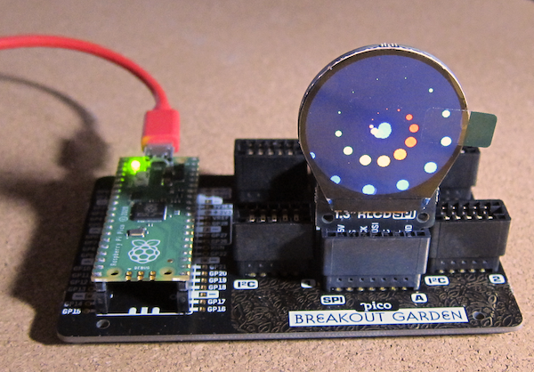
The Pimoroni PICO Breakout Garden Base has a socket for a Raspberry Pi PICO (available from Pimoroni with headers pre-soldered) plus four I2C sockets and two SPI sockets compatible with the Pimoroni breakout garden breakouts. Pimoroni also do a Breakout Garden to QT/QWIIC adapter.

This allows soldering free development (assuming you buy the PICO with headers attached) and reuse of the various breakouts (with other PICOs including the Explorer Base or Raspberry Pis).
There are libraries for C++, MicroPython and Circuit Python.


Before fitting the Raspberry Pi PICO to the Breakout Garden Base, I would recommend testing the PICO. The Blink program (that flashes the PICO's built in LED) is a good test.
The Breakout Garden Base has two rows of sockets to take the pins soldered to the Raspberry Pi PICO microcontroller. Match the orientation of the Pico with the drawing between the sockets and align the pins on the Raspberry Pi PICO with the holes in the sockets and gently and evenly apply pressure until the PICO is in place.
To use the I2C and SPI sockets on the base, Pimoroni have created a custom UF2 file including the required drivers. Follow the instructions here: https://learn.pimoroni.com/tutorial/hel/getting-started-with-pico
If you find the latest Pimoroni UF2 version does not work as expected, use the Update Firmware option on Thonny to return to a vanilla flavour UF2 and reload the Blink example.
It might be that the latest version has introduced a bug in the Breakout Garden handling. Download and install an earlier version of the Pimoroni UF2.
It is very useful to add parts of the Blink example to your code when testing to show that the code is working.
There are examples for a number of the breakouts available.
https://shop.pimoroni.com/products/pico-breakout-garden-base
https://shop.pimoroni.com/products/raspberry-pi-pico?variant=32402092326995
https://shop.pimoroni.com/collections/breakout-garden
https://shop.pimoroni.com/products/breakout-garden-to-qwiic-adaptor
https://en.wikipedia.org/wiki/I%C2%B2C
https://en.wikipedia.org/wiki/Serial_Peripheral_Interface
https://learn.pimoroni.com/tutorial/hel/getting-started-with-pico
https://github.com/pimoroni/pimoroni-pico/releases
https://github.com/pimoroni/pimoroni-pico/tree/main/micropython/examples
It has been a while since I last showed off my collection of Raspberry Pi computers.

This is not quite the full collection, the Raspberry Pi Zero with the official Raspberry Pi camera is, well not to hand.
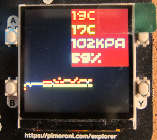
The Raspberry Pi Pico Explorer is a plug-in board that provides a number of built-in devices including a 240x240 colour display, four buttons, a piezo buzzer, two I2S Breakout Garden sockets and sockets connected to the Pico's pins plus a small solderless breadboard.
A Raspberry Pi Pico with pre-soldered headers makes development easy without needing to solder delicate electronics.