Saturday, 9 July 2022

CircuitPython and MicroPython - – start file differences

CircuitPython and MicroPython have many similarities, but there are some major differences.

One of the most fundamental are the names of the files executed when the board is powered up.

Start up sequence

MIcroPython 

MIcroPython looks for two files in a set order in the root of its filesystem.

  • boot.py – this file is run when power is first applied to the board or when the board is reset. Probably not of interest in general unless you are modifying MicroPython.
  • main.py – this is the file that is either your program or starts your program. If it is present, it is run after the code in the boot.py file.

CircuitPython

CircuitPython looks for the following files in this order:

  • •code.txt
  • •code.py
  • •main.txt
  • •main.py.

References

https://learn.adafruit.com/getting-started-with-raspberry-pi-pico-circuitpython/micropython-or-circuitpython

https://github.com/adafruit/circuitpython#differences-from-micropython

https://docs.circuitpython.org/en/latest/README.html#differences-from-micropython


Sunday, 20 February 2022

PICO Breakout Garden Base

The Pimoroni PICO Breakout Garden Base has a socket for a Raspberry Pi PICO (available from Pimoroni with headers pre-soldered) plus four I2C sockets and two SPI sockets compatible with the Pimoroni breakout garden breakouts. Pimoroni also do a Breakout Garden to QT/QWIIC adapter.


This allows soldering free development (assuming you buy the PICO with headers attached) and reuse of the various breakouts (with other PICOs including the Explorer Base or Raspberry Pis).

There are libraries for C++, MicroPython and Circuit Python.

Installation

Hardware

Breakout Garden Base, self adhesive feet and a Raspberry Pi PICO.
The printed paws on the underside show where the self adhesive feet go.


Before fitting the Raspberry Pi PICO to the Breakout Garden Base, I would recommend testing the PICO. The Blink program (that flashes the PICO's built in LED) is a good test.

The Breakout Garden Base has two rows of sockets to take the pins soldered to the Raspberry Pi PICO microcontroller. Match the orientation of the Pico with the drawing between the sockets and align the pins on the Raspberry Pi PICO with the holes in the sockets and gently and evenly apply pressure until the PICO is in place.

Software

To use the I2C and SPI sockets on the base, Pimoroni have created a custom UF2 file including the required drivers. Follow the instructions here: https://learn.pimoroni.com/tutorial/hel/getting-started-with-pico

If you find the latest Pimoroni UF2 version does not work as expected, use the Update Firmware option on Thonny to return to a vanilla flavour UF2 and reload the Blink example.

It might be that the latest version has introduced a bug in the Breakout Garden handling. Download and install an earlier version of the Pimoroni UF2.

It is very useful to add parts of the Blink example to your code when testing to show that the code is working.

There are examples for a number of the breakouts available.

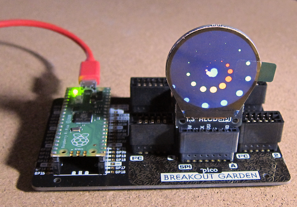
1.3" SPI Colour Round LCD example in operation.

References

https://shop.pimoroni.com/products/pico-breakout-garden-base

https://shop.pimoroni.com/products/raspberry-pi-pico?variant=32402092326995

https://shop.pimoroni.com/collections/breakout-garden

https://shop.pimoroni.com/products/breakout-garden-to-qwiic-adaptor

https://en.wikipedia.org/wiki/I%C2%B2C

https://en.wikipedia.org/wiki/Serial_Peripheral_Interface

https://learn.pimoroni.com/tutorial/hel/getting-started-with-pico

https://github.com/pimoroni/pimoroni-pico/releases

https://github.com/pimoroni/pimoroni-pico/tree/main/micropython/examples


Sunday, 23 January 2022

Raspberry Pi Collection 2021

 It has been a while since I last showed off my collection of Raspberry Pi computers.

Left column:
Right column

This is not quite the full collection, the Raspberry Pi Zero with the official Raspberry Pi camera is, well not to hand.

Monday, 17 January 2022

Raspberry Pi Pico Explorer

The Raspberry Pi Pico Explorer is a plug-in board that provides a number of built-in devices including a 240x240 colour display, four buttons, a piezo buzzer, two I2S Breakout Garden sockets and sockets connected to the Pico's pins plus a small solderless breadboard.

A Raspberry Pi Pico with pre-soldered headers makes development easy without needing to solder delicate electronics.


Assembly was easy, care being taken to make sure all the pins aligned with the corresponding holes in the socket on the board.

Updating the Firmware

To use the components on the Explorer board, Pimoroni has created a custom UF2 file, including the required drivers. As of 03/01/2022 the latest version of the Pimoroni firmware (0.3.2) does not work, use version 0.3.1. This might not be the case for other boards.

Use the Update Firmware option on Thonny to return to a vanilla flavour and the Blink example if the current Pimoroni version does not work as expected. Select an earlier version of the UF2 and try again.

There is an example that measures the cpu temperature which is then displayed as text and a bar graph.
The next stage was to make use of the Breakout Garden sockets and add some breakout units. 
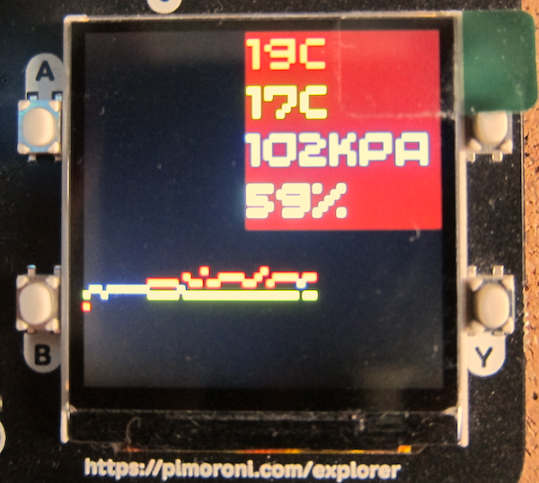
To provide some measurements, a BME680 environmental sensor was added to the right hand socket. In the left hand socket is a rotary encoder with a built in RGB LED.
The two sockets allow the addition of two breakouts. PIMORONI have a range of breakouts, including additional convertors that allow connection to STEMMA or Qwiic devices.

The BME680 breakout is an older model, the current version includes a built in STEMMA or Qwiic connector.
The example program was modified to get the temperature, pressure and humidity from the BME680 sensor plus the cpi temperature.

The code to set the encoder's RGB LED colour was also added.
The graph code was designed to display both the cpu temperature and the sensor temperature.

Finally a maximum and minimum sensor temperature was added to the display.

Code

Do check the indenting as Python uses the indenting to define the structure of the program.

import machine
import utime

from breakout_bme68x import BreakoutBME68X
from pimoroni_i2c import PimoroniI2C

PINS_BREAKOUT_GARDEN = {"sda": 4, "scl": 5}
PINS_PICO_EXPLORER = {"sda": 20, "scl": 21}

i2c = PimoroniI2C(**PINS_PICO_EXPLORER)

# Pico Explorer boilerplate
import picoexplorer as display
width = display.get_width()
height = display.get_height()
display_buffer = bytearray(width * height * 2)
display.init(display_buffer)

# BME68x configuration
bme = BreakoutBME68X(i2c)
#bme.configure(FILTER_COEFF_3, STANDBY_TIME_1000_MS, OVERSAMPLING_16X, OVERSAMPLING_2X, OVERSAMPLING_1X)

# reads from Pico's temp sensor and converts it into a more manageable number
sensor_temp = machine.ADC(4)
conversion_factor = 3.3 / (65535)

# Set up text areas
blockHeight = 33
textBlocks = 8
textArea=list()
for x in range(textBlocks):
    if(textBlocks>4):
        if(x<4):
            textArea.append([10,(blockHeight*x)+1,120,blockHeight])        
        else:
            textArea.append([120,(blockHeight*(x-4))+1,120,blockHeight])
    else:
        textArea.append([120,(blockHeight*x)+1,120,blockHeight])

# Set up background and text pens
background_pen = display.create_pen(0,0,0)
cpu_temp_pen = display.create_pen(255, 64, 64)
bme_temp_pen = display.create_pen(64, 255, 64)
pressure_pen = display.create_pen(64, 64, 255)
humidity_pen = display.create_pen(0, 255, 255)

# Define number of pixels for the graph points
graph_element_size = 1
graph_y_scale = 4

def drawTemp(i,cpu_temp,sensor_temp):
    diff = abs((cpu_temp*graph_element_size)-(sensor_temp*graph_element_size))
    if(diff<graph_element_size):
        display.set_pen(255,255,0)
        display.rectangle(i, height - (cpu_temp * graph_y_scale), graph_element_size,graph_element_size)
    else:
        display.set_pen(cpu_temp_pen)
        display.rectangle(i, height - (cpu_temp * graph_y_scale), graph_element_size,graph_element_size)
        display.set_pen(bme_temp_pen)
        display.rectangle(i, height - (int(sensor_temp) * graph_y_scale), graph_element_size,graph_element_size)
    
def writeInBlock(text, location, pen, paper, size):
    # Draw background to clear display area
    display.set_pen(paper)
    display.rectangle(location[0],location[1],location[2],location[3])
    # Write text in location one pixel left and down
    display.set_pen(pen)
    display.text(text, location[0]+1,location[1]+1,100,size)
    
# Initialise run variables
i = 0
count = 0
max_temp = 0
min_temp = 100

while True:
    # the following two lines do some maths to convert the number from the temp sensor into celsius
    reading = sensor_temp.read_u16() * conversion_factor
    temperature = round(27 - (reading - 0.706) / 0.001721)
    bmetemp, pressure, humidity, gas_resistance, status, gas_index, meas_index = bme.read()
    max_temp=max(max_temp,bmetemp)
    min_temp=min(min_temp,bmetemp)
    
    # Clear the display and reset counter if the graph reaches the right hand side
    if i >= (width + 1):
        i = 0
        display.set_pen(0, 0, 0)
        display.clear()

    # Draw graph element
    drawTemp(i,temperature,bmetemp)

    writeInBlock("{:.0f}".format(temperature) + "c", textArea[0],cpu_temp_pen,background_pen,4)
    writeInBlock("{:.0f}".format(bmetemp) + "c", textArea[1],bme_temp_pen,background_pen,4)
    writeInBlock("{:.0f}".format(pressure/1000) + "kPa", textArea[2],pressure_pen,background_pen,3)
    writeInBlock("{:.0f}".format(humidity)+"%", textArea[3],humidity_pen,background_pen,4)
    writeInBlock("Mx {:.0f}".format(max_temp) + "c", textArea[4],bme_temp_pen,background_pen,3)
    writeInBlock("Mn {:.0f}".format(min_temp) + "c", textArea[5],bme_temp_pen,background_pen,3)
    # time to update the display
    display.update()

    # waits for 5 seconds
    utime.sleep(1)

    # Set next graph element location
    i+=graph_element_size


Sunday, 9 January 2022

Raspberry Pi 4 8GB and the Pimoroni Heatsink case

The 8GB version of the Raspberry Pi 4 came out in 2021, and like the 4GB version I decided that I would use a Pimoroni Heat Sink case, this one in red (red ones go faster). 


I also bought an official Raspberry Pi 4 power supply.
I also remembered to photograph the board before assembly.
The main set of ports (left to right) USB-C power in, 4K Micro HDMI x 2, combo audio and TV.
Board and power supply.
Case components.
Insides showing where the heat sinks connect to the board.


Saturday, 8 January 2022

Installing CLANG on a Raspberry Pi

The following uses an 8GB Raspberry Pi 4.


Update and upgrade your installation

sudo apt update
sudo apt upgrade

Install CLANG

apt-get install clang-format clang-tidy clang-tools clang libc++-dev libc++1 libc++abi-dev libc++abi1 libclang-dev libclang1 liblldb-dev libllvm-ocaml-dev libomp-dev libomp5 lld lldb llvm-dev llvm-runtime llvm python-clang

Note: LLVM suggested apt call includes clangd, however it does not appear on the “current” Raspbian distribution (though I noted my version of CLANG is version 7 so later distributions might contain it).

Check it is in place.

clang++ --version


clang version 7.0.1-8+rpi3+deb10u2 (tags/RELEASE_701/final)
Target: armv6k-unknown-linux-gnueabihf
Thread model: posix
InstalledDir: /usr/bin

Hello World

Create a C++ source file
#include <iostream>
int main(){
std::cout<<"Hello world\n";
return 0;
}

Save the file to a specific folder (I chose ~/Documents/Cplusplus/helloworld )

Change the working folder to its location
cd ~/Documents/Cplusplus/helloworld

Compile:
clang++ -std=c++17 -Wall -pedantic helloworld .cpp -o helloworld
Run
./helloworld


Install Visual Studio Code (Other IDEs are available)

Raspberry Pi has Visual Studio Code in its repository
sudo apt install code

Open Visual Studio Code and install the install the C/C++ extension (C/C++ from Microsoft).

Configuring Visual Studio Code

Other descriptions of configuring Visual Studio include additional editing of files, but the Raspberry Pi repository seems to cover a lot of it.
Open the folder in Visual Studio.
Open the CPP file.

Click on Run and select Start Debugging.
From the list of environments select C++(GDB/LLDB)
Select g++.exe - Build and debug active file.
This creates a new folder named .vscode in the current folder.
Within that folder are two JSON files: tasks.json and launch.json
The file tasks.json contains the arguments and the location of the clang compiler front end.


{
"tasks": [
{
"type": "cppbuild",
"label": "C/C++: clang++ build active file",
"command": "/usr/bin/clang++",
"args": [
"-fdiagnostics-color=always",
"-g",
"${file}",
"-o",
"${fileDirname}/${fileBasenameNoExtension}"
],
"options": {
"cwd": "${fileDirname}"
},
"problemMatcher": [
"$gcc"
],
"group": {
"kind": "build",
"isDefault": true
},
"detail": "Task generated by Debugger."
}
],
"version": "2.0.0"
}


Use the above file as a reference.
The launch.json file contains information about what happens when Visual Studio Code starts to run the compilation.
{
// Use IntelliSense to learn about possible attributes.
// Hover to view descriptions of existing attributes.
// For more information, visit: https://go.microsoft.com/fwlink/?linkid=830387
"version": "0.2.0",
"configurations": [
{
"name": "clang++ - Build and debug active file",
"type": "cppdbg",
"request": "launch",
"program": "${fileDirname}/${fileBasenameNoExtension}",
"args": [],
"stopAtEntry": false,
"cwd": "${fileDirname}",
"environment": [],
"externalConsole": false,
"MIMode": "lldb",
"targetArchitecture": "ARM64",
"setupCommands": [
{
"description": "Enable pretty-printing for gdb",
"text": "-enable-pretty-printing",
"ignoreFailures": true
}
],
"preLaunchTask": "C/C++: clang++ build active file",
"miDebuggerPath": "/usr/bin/lldb-mi"
}
]
}


The key element that is not in the default configurations elements is the targetArchitecture:
"targetArchitecture": "ARM64"
Add this to the file as shown above.
This removes the “Warning: Debuggee TargetArchitecture not detected, assuming x86_64.” warning message.


References

https://apt.llvm.org/
https://code.visualstudio.com/docs/setup/raspberry-pi
https://www.raspberrypi.com/news/visual-studio-code-comes-to-raspberry-pi/
https://solarianprogrammer.com/2018/04/22/raspberry-pi-raspbian-install-clang-compile-cpp-17-programs/
https://solarianprogrammer.com/2021/06/11/install-clang-windows-msys2-mingw-w64/
https://johnnn.tech/q/vscode-lldb-on-macos-error-when-starting-debugging-session/
https://code.visualstudio.com/updates/v1_50#_linux-arm-builds


Sunday, 2 January 2022

WIZnet W5100S-EVB-Pico Ethernet microcontroller

 The W5100S-EVB-Pico microcontroller board is pin compatible with the Raspberry Pi Pico and uses the same RP2040 microcontroller. It is integrated with the WIZnet W5100S ethernet controller.


It has a built in RJ45 ethernet socket.

There are examples in Circuit Python and C/C++.

As an exercise I decided to first try using C/C++ as the development language and a Windows 10 machine as the development machine (cross compiling to the ARM based RP2040).

I followed the instructions to install CMAKE, however there is an ongoing issue with CMAKE version 3.21+ that causes a 

AR10B2~1.EXE: error: n++CMakeFiles/blink.dir/blink.c.obj: No such file or directory

error when executing the nmake line of the instructions.

It is suggested that an earlier version of the CMAKE tool is installed. Version 3.20 seems to work. 

I tested the basic operation of the board by using the Blink example from the Raspberry Pi Pico examples.

WIZnet examples

The instructions for retrieving the examples from WIZnet are not quite as clear.
Eventually I managed to GIT clone the files. However it was quite difficult to get it to actually compile because of the folder structure.

In the end I started from scratch with a new folder structure and copied the files as required.

The default compiler for CMake needs to have been set (I ended up setting it via Visual Studio Code).

Initially the Blink example was included as I knew that worked. Once that worked, the CMakeLists.txt file was edited to include all the components required (see example below).

This included the patches files. Unfortunately that failed with an incorrect version error.

Compiling without the patches lead to pages of missing methods errors.
Examining the first patch file highlighted the change being made, selection of the Ethernet device chip set. The supplied code selects the W5500 chip set - the rest of the code only contains the W5100S chip set code, it is not selected and so methods are missing.

Manually updating the chip selection (as shown in the patch file) to the W5100S chip set solved the issue with the missing methods.

Once compiled, the EVB was put into bootloader mode and the UF2 was copied over.

Attempting to browse to the machine based on the default IP address failed.

The default IP address {192, 168, 11, 2} is outside the usual "local" range of a domestic router (192.168.1.X). This was changed in the w5x00_http_server.c file to a suitable number.
For my system I chose 192.168.1.234. 
Note: for a permanent solution, the IP address should be generated by the DHCP of the network or the selected IP address should be excluded from the range available to the DHCP server.
message("Start from scratch")
cmake_minimum_required(VERSION 3.10)
#include(rp2040_hat_c-patch.cmake)
include(pico_sdk_import.cmake)
include(rp2040_hat_c_sdk_version.cmake)
project(blink C CXX ASM)
set(CMAKE_C_STANDARD 11)
set(CMAKE_CXX_STANDARD 17)

set(PICO_EXAMPLES_PATH ${PROJECT_SOURCE_DIR})
pico_sdk_init()
if(NOT DEFINED WIZNET_DIR)
    set(WIZNET_DIR ${CMAKE_SOURCE_DIR}/libraries/ioLibrary_Driver)
    message(STATUS "WIZNET_DIR = ${WIZNET_DIR}")
endif()

if(NOT DEFINED MBEDTLS_LIB_DIR)
    set(MBEDTLS_LIB_DIR ${CMAKE_SOURCE_DIR}/libraries/mbedtls)
    message(STATUS "MBEDTLS_LIB_DIR = ${MBEDTLS_LIB_DIR}")
endif()

if(NOT DEFINED PORT_DIR)
    set(PORT_DIR ${CMAKE_SOURCE_DIR}/port)
    message(STATUS "PORT_DIR = ${PORT_DIR}")
endif()
# Turn off mbedtls test mode 
set(ENABLE_PROGRAMS OFF CACHE BOOL "Build mbedtls programs")
set(ENABLE_TESTING OFF CACHE BOOL "Build mbedtls testing")
add_definitions(-DMBEDTLS_CONFIG_FILE="${PORT_DIR}/mbedtls/inc/ssl_config.h")
add_definitions(-DSET_TRUSTED_CERT_IN_SAMPLES)

add_subdirectory(server)

# Add libraries in subdirectories
add_subdirectory(${CMAKE_SOURCE_DIR}/libraries)
add_subdirectory(${MBEDTLS_LIB_DIR})
add_subdirectory(${PORT_DIR})
include(example_auto_set_url.cmake)

add_compile_options(-Wall
        -Wno-format          # int != int32_t as far as the compiler is concerned because gcc has int32_t as long int
        -Wno-unused-function # we have some for the docs that aren't called
        -Wno-maybe-uninitialized
        )
message("PICO SDK: ${PICO_SDK_VERSION_STRING}")