Sunday, 9 January 2022

Raspberry Pi 4 8GB and the Pimoroni Heatsink case

The 8GB version of the Raspberry Pi 4 came out in 2021, and like the 4GB version I decided that I would use a Pimoroni Heat Sink case, this one in red (red ones go faster). 


I also bought an official Raspberry Pi 4 power supply.
I also remembered to photograph the board before assembly.
The main set of ports (left to right) USB-C power in, 4K Micro HDMI x 2, combo audio and TV.
Board and power supply.
Case components.
Insides showing where the heat sinks connect to the board.


Saturday, 8 January 2022

Installing CLANG on a Raspberry Pi

The following uses an 8GB Raspberry Pi 4.


Update and upgrade your installation

sudo apt update
sudo apt upgrade

Install CLANG

apt-get install clang-format clang-tidy clang-tools clang libc++-dev libc++1 libc++abi-dev libc++abi1 libclang-dev libclang1 liblldb-dev libllvm-ocaml-dev libomp-dev libomp5 lld lldb llvm-dev llvm-runtime llvm python-clang

Note: LLVM suggested apt call includes clangd, however it does not appear on the “current” Raspbian distribution (though I noted my version of CLANG is version 7 so later distributions might contain it).

Check it is in place.

clang++ --version


clang version 7.0.1-8+rpi3+deb10u2 (tags/RELEASE_701/final)
Target: armv6k-unknown-linux-gnueabihf
Thread model: posix
InstalledDir: /usr/bin

Hello World

Create a C++ source file
#include <iostream>
int main(){
std::cout<<"Hello world\n";
return 0;
}

Save the file to a specific folder (I chose ~/Documents/Cplusplus/helloworld )

Change the working folder to its location
cd ~/Documents/Cplusplus/helloworld

Compile:
clang++ -std=c++17 -Wall -pedantic helloworld .cpp -o helloworld
Run
./helloworld


Install Visual Studio Code (Other IDEs are available)

Raspberry Pi has Visual Studio Code in its repository
sudo apt install code

Open Visual Studio Code and install the install the C/C++ extension (C/C++ from Microsoft).

Configuring Visual Studio Code

Other descriptions of configuring Visual Studio include additional editing of files, but the Raspberry Pi repository seems to cover a lot of it.
Open the folder in Visual Studio.
Open the CPP file.

Click on Run and select Start Debugging.
From the list of environments select C++(GDB/LLDB)
Select g++.exe - Build and debug active file.
This creates a new folder named .vscode in the current folder.
Within that folder are two JSON files: tasks.json and launch.json
The file tasks.json contains the arguments and the location of the clang compiler front end.


{
"tasks": [
{
"type": "cppbuild",
"label": "C/C++: clang++ build active file",
"command": "/usr/bin/clang++",
"args": [
"-fdiagnostics-color=always",
"-g",
"${file}",
"-o",
"${fileDirname}/${fileBasenameNoExtension}"
],
"options": {
"cwd": "${fileDirname}"
},
"problemMatcher": [
"$gcc"
],
"group": {
"kind": "build",
"isDefault": true
},
"detail": "Task generated by Debugger."
}
],
"version": "2.0.0"
}


Use the above file as a reference.
The launch.json file contains information about what happens when Visual Studio Code starts to run the compilation.
{
// Use IntelliSense to learn about possible attributes.
// Hover to view descriptions of existing attributes.
// For more information, visit: https://go.microsoft.com/fwlink/?linkid=830387
"version": "0.2.0",
"configurations": [
{
"name": "clang++ - Build and debug active file",
"type": "cppdbg",
"request": "launch",
"program": "${fileDirname}/${fileBasenameNoExtension}",
"args": [],
"stopAtEntry": false,
"cwd": "${fileDirname}",
"environment": [],
"externalConsole": false,
"MIMode": "lldb",
"targetArchitecture": "ARM64",
"setupCommands": [
{
"description": "Enable pretty-printing for gdb",
"text": "-enable-pretty-printing",
"ignoreFailures": true
}
],
"preLaunchTask": "C/C++: clang++ build active file",
"miDebuggerPath": "/usr/bin/lldb-mi"
}
]
}


The key element that is not in the default configurations elements is the targetArchitecture:
"targetArchitecture": "ARM64"
Add this to the file as shown above.
This removes the “Warning: Debuggee TargetArchitecture not detected, assuming x86_64.” warning message.


References

https://apt.llvm.org/
https://code.visualstudio.com/docs/setup/raspberry-pi
https://www.raspberrypi.com/news/visual-studio-code-comes-to-raspberry-pi/
https://solarianprogrammer.com/2018/04/22/raspberry-pi-raspbian-install-clang-compile-cpp-17-programs/
https://solarianprogrammer.com/2021/06/11/install-clang-windows-msys2-mingw-w64/
https://johnnn.tech/q/vscode-lldb-on-macos-error-when-starting-debugging-session/
https://code.visualstudio.com/updates/v1_50#_linux-arm-builds


Sunday, 2 January 2022

WIZnet W5100S-EVB-Pico Ethernet microcontroller

 The W5100S-EVB-Pico microcontroller board is pin compatible with the Raspberry Pi Pico and uses the same RP2040 microcontroller. It is integrated with the WIZnet W5100S ethernet controller.


It has a built in RJ45 ethernet socket.

There are examples in Circuit Python and C/C++.

As an exercise I decided to first try using C/C++ as the development language and a Windows 10 machine as the development machine (cross compiling to the ARM based RP2040).

I followed the instructions to install CMAKE, however there is an ongoing issue with CMAKE version 3.21+ that causes a 

AR10B2~1.EXE: error: n++CMakeFiles/blink.dir/blink.c.obj: No such file or directory

error when executing the nmake line of the instructions.

It is suggested that an earlier version of the CMAKE tool is installed. Version 3.20 seems to work. 

I tested the basic operation of the board by using the Blink example from the Raspberry Pi Pico examples.

WIZnet examples

The instructions for retrieving the examples from WIZnet are not quite as clear.
Eventually I managed to GIT clone the files. However it was quite difficult to get it to actually compile because of the folder structure.

In the end I started from scratch with a new folder structure and copied the files as required.

The default compiler for CMake needs to have been set (I ended up setting it via Visual Studio Code).

Initially the Blink example was included as I knew that worked. Once that worked, the CMakeLists.txt file was edited to include all the components required (see example below).

This included the patches files. Unfortunately that failed with an incorrect version error.

Compiling without the patches lead to pages of missing methods errors.
Examining the first patch file highlighted the change being made, selection of the Ethernet device chip set. The supplied code selects the W5500 chip set - the rest of the code only contains the W5100S chip set code, it is not selected and so methods are missing.

Manually updating the chip selection (as shown in the patch file) to the W5100S chip set solved the issue with the missing methods.

Once compiled, the EVB was put into bootloader mode and the UF2 was copied over.

Attempting to browse to the machine based on the default IP address failed.

The default IP address {192, 168, 11, 2} is outside the usual "local" range of a domestic router (192.168.1.X). This was changed in the w5x00_http_server.c file to a suitable number.
For my system I chose 192.168.1.234. 
Note: for a permanent solution, the IP address should be generated by the DHCP of the network or the selected IP address should be excluded from the range available to the DHCP server.
message("Start from scratch")
cmake_minimum_required(VERSION 3.10)
#include(rp2040_hat_c-patch.cmake)
include(pico_sdk_import.cmake)
include(rp2040_hat_c_sdk_version.cmake)
project(blink C CXX ASM)
set(CMAKE_C_STANDARD 11)
set(CMAKE_CXX_STANDARD 17)

set(PICO_EXAMPLES_PATH ${PROJECT_SOURCE_DIR})
pico_sdk_init()
if(NOT DEFINED WIZNET_DIR)
    set(WIZNET_DIR ${CMAKE_SOURCE_DIR}/libraries/ioLibrary_Driver)
    message(STATUS "WIZNET_DIR = ${WIZNET_DIR}")
endif()

if(NOT DEFINED MBEDTLS_LIB_DIR)
    set(MBEDTLS_LIB_DIR ${CMAKE_SOURCE_DIR}/libraries/mbedtls)
    message(STATUS "MBEDTLS_LIB_DIR = ${MBEDTLS_LIB_DIR}")
endif()

if(NOT DEFINED PORT_DIR)
    set(PORT_DIR ${CMAKE_SOURCE_DIR}/port)
    message(STATUS "PORT_DIR = ${PORT_DIR}")
endif()
# Turn off mbedtls test mode 
set(ENABLE_PROGRAMS OFF CACHE BOOL "Build mbedtls programs")
set(ENABLE_TESTING OFF CACHE BOOL "Build mbedtls testing")
add_definitions(-DMBEDTLS_CONFIG_FILE="${PORT_DIR}/mbedtls/inc/ssl_config.h")
add_definitions(-DSET_TRUSTED_CERT_IN_SAMPLES)

add_subdirectory(server)

# Add libraries in subdirectories
add_subdirectory(${CMAKE_SOURCE_DIR}/libraries)
add_subdirectory(${MBEDTLS_LIB_DIR})
add_subdirectory(${PORT_DIR})
include(example_auto_set_url.cmake)

add_compile_options(-Wall
        -Wno-format          # int != int32_t as far as the compiler is concerned because gcc has int32_t as long int
        -Wno-unused-function # we have some for the docs that aren't called
        -Wno-maybe-uninitialized
        )
message("PICO SDK: ${PICO_SDK_VERSION_STRING}")

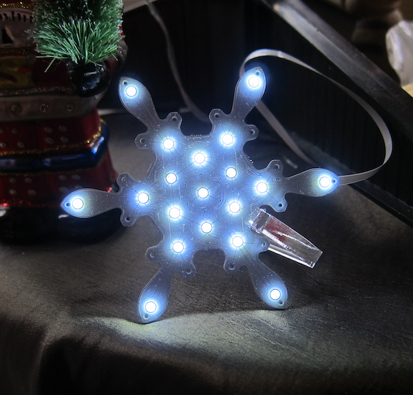
PIMORONI Snowflake Solo

 Pimoroni released their Snowflake product based on a design by Lucky Resistor a number of years ago.


I thought it looked great but was not sure if five of them would be a bit overwhelming.

This year they introduced the Snowflake Solo, a single Snowflake board and a controller board all on a single beautifully crafted PCB.

The Snowflake Solo comes on a single etched PCB and includes a 200mm flat cable to run between the control board and the Snowflake.
Half etched supports hold the control board and the snowflake onto the PCB. There are instructions here on how to separate the components from the carrier board. The important thing is to bend the carrier and not the snowflake/controller board.

Once the two boards  are separated they need to be connected. The connectors on both boards are identical (note that there are two connectors on the snowflake - an In and an Out).
On the control board and the In connector on the snowflake, flip up the connector to open it, insert the cable with the blue side upwards, and close the connector.

The control board has a micro-usb socket for power, I used one of my Raspberry Pi Zero mains adaptors, any micro-USB charger should be fine.

The snowflake is programmed with a number of different patterns, these can be selected by clicking the centre button on the control board. Click it once to select change mode, then click it a number of times to select the rquired mode.

The acrylic stand is quite a tight fit.


Saturday, 26 June 2021

Temperature measuring Web Server

So, having had the Pimoroni Breakout Garden for a while and having used it as a temperature measurement device with a BME680 and display, I needed to measure the temperature and compare it with the temperature measured  by the analogue sensor of an Adafruit PyPortal and the CPU temperature.

The BME680 results are affected by the heat generated by the CPU, and a correction formula based on the CPU temperature was used to compensate for the CPU temperature.

An alternative is to separate the temperature sensor from the CPU.

This was achieved using a Breakout Garden to Stemma QT/QWIIC adapter and STEMMA QT / Qwiic to Breakout Garden Adapter  joined by a JST to JST cable. A BMP280 breakout was plugged in at one end, and the other plugged into the Breakout Garden. This should provide sufficient thermal isolation from the hot CPU.


Software installation

The Python library for the BMP280 temperature, pressure and altitude sensor is available via PIP. As with all installations, check if pip is for the now obsolete Python 2.x or Python 3.x. If the former, then use pip3 (that is the case on my Raspberry Pi Zero development systerm).

sudo pip3 install bmp280

The easiest way to make the data available to an Internet connectable device is by making the temperature measuring Raspberry Pi a web server.

The Flask library is similarly installed with pip. Note Flask starts with a capital letter
sudo pip3 install -U Flask

Web Server

This is a very simple web server, it has two  pages - /temperature and /json.

from flask import Flask, render_template
import time
import datetime
import json
from bmp280 import BMP280

try:
    from smbus2 import SMBus
except ImportError:
    from smbus import SMBus
app = Flask(__name__)

@app.route('/temperature')
def temperature():
    now = datetime.datetime.now()
    timeString = now.strftime("%Y-%m-%d %H:%M")
    temperature = bmp280.get_temperature()
    temp = '{:05.2f}*C'.format(temperature)
    templateData = {
      'temperature' : temp,
      'time': timeString
      }
    return render_template('temperature.html', **templateData)

@app.route('/json')
def tempjson():
    now = datetime.datetime.now()
    timeString = now.strftime("%Y-%m-%d %H:%M")
    temperature = bmp280.get_temperature()
    temp = '{:05.2f}'.format(temperature)
    templateData = {
      'temperature' : temp,
      'time': timeString
      }

    return json.dumps(templateData)

if __name__ == '__main__':
    bus = SMBus(1)
    bmp280 = BMP280(i2c_dev=bus)
    app.run(debug=True, host='0.0.0.0')

References


Saturday, 12 June 2021

Raspberry Pi Pico and MicroPython

Installing MicroPython


To install or upgrade MicroPython on a Pico there are three steps.

1. Download the UF2 file. There is a vanilla version available from micropython.org, or if you are using one of Pimoroni's boards then you can select one of the UF2 files with all their libraries preinstalled here.

2. Put the Pico into BootLoader mode by unplugging it, hold the BOOTSEL button down and then plugging it back in. The Pico will then appear as a USB device on the host machine.

3. Copy the UF2 file into the new USB device

Once the file has been copied over, the USB device will disappear.

Testing the MicroPython

As the Pico has no built-in display, it can only communicate via the USB. The MicroPython firmware has a built-in serial port available over the USB.

To access it, the popular Minicom package is used.

Install it on your Pi using:

sudo apt install minicom

Next, identify the serial port.

The Pico should appear as a port of the form /dev/ttyACM.

Use 

ls /dev/tty*

If it is unclear which port is the Pico, unplug it and try again, identifying which device disappears.

Connect to the MicroPython running on the Pico using:

minicom -o -D /dev/ttyACM0

This should display the Minicom opening text:

Welcome to minicom 2.7.1
OPTIONS: I18n 
Compiled on Aug 13 2017, 15:25:34.
Port /dev/ttyACM0, 07:39:31
Press CTRL-A Z for help on special keys

You now need to soft reboot, press Control and D. This will display information about the installed MicroPython and the prompt >>>.

MPY: soft reboot

MicroPython v1.15 on 2021-04-18; Raspberry Pi Pico with RP2040

Type "help()" for more information.

>>>

To test the MicoPython, try the classic:

>>> print("hello")

hello

>>>

This shows that MicroPython is running successfully on your Pico.

Control A then Z brings up help.

Control X closes Minicom.

References

https://micropython.org/download/rp2-pico/rp2-pico-latest.uf2

https://github.com/pimoroni/pimoroni-pico/releases

https://datasheets.raspberrypi.org/pico/raspberry-pi-pico-python-sdk.pdf

https://en.wikipedia.org/wiki/Minicom


Friday, 21 May 2021

Adafruit Trinkey

The Adafruit Trinkey is a tiny USB key format microcontroller with four Neopixels and an M0 processor.


The end opposite the USB contact can function as two touch sensitive buttons.

I bought mine from Pimoroni.

When plugged into the USB port of my Debian laptop, it failed to register. I thought it might be an issue with connecting to an elderly ex-Windows laptop. So I tried it on a Windows laptop. Still it did not register. The Neopixels worked, and the touch sensors started and stopped the display.

However, when set to Boot Mode (double press on the reboot button) it registered as a USB device.

I then downloaded the latest version of CircuitPython from https://circuitpython.org/board/neopixel_trinkey_m0/

This was then copied to the device which then causes the device to restart. The device now appeared as a USB memory device.

Programming

CircuitPython devices are simple to program, appearing as a USB memory device. Saving a new file to the device causes it to restart. Generally the file code.py is executed on starting.

Adafruit's recommendation is to use the Mu editor. This writes directly to the CircuitPython device. It does however mean you need to be particularly careful that you have a copy of the code somewhere.

To make my life easier, I put together a simple Visual Studio program to copy specific code.py files from specific folders. I then edited the code using Visual Studio Code.

Example code

The example code is derived from the code from the Neo Trinkey Zoom Short Cut project (see references)

import time
import board
import neopixel

#  setup for onboard neopixels
pixel_pin = board.NEOPIXEL
num_pixels = 4

pixels = neopixel.NeoPixel(pixel_pin, num_pixels, brightness=0.05, auto_write=False)

def wheel(pos):
    # Input a value 0 to 255 to get a color value.
    # The colours are a transition r - g - b - back to r.
    if pos < 0 or pos > 255:
        return (0, 0, 0)
    if pos < 85:
        return (255 - pos * 3, pos * 3, 0)
    if pos < 170:
        pos -= 85
        return (0, 255 - pos * 3, pos * 3)
    pos -= 170
    return (pos * 3, 0, 255 - pos * 3)

def rainbow_cycle(wait):
    for j in range(255):
        for i in range(num_pixels):
            rc_index = (i * 256 // num_pixels) + j
            pixels[i] = wheel(rc_index & 255)
        pixels.show()
        time.sleep(wait)

while True:
    rainbow_cycle(0.001)

References

https://www.adafruit.com/product/4870
https://circuitpython.org/board/neopixel_trinkey_m0/