The Adafruit Metro RP2040 takes the Arduino format and adds the Raspberry Pi RP2040.


The Adafruit Metro RP2040 takes the Arduino format and adds the Raspberry Pi RP2040.

PIMORONI have released a clever board that combines a Pico W with a second RP2040 chip and supporting electronics complete with an HDMI shaped output, a 3.5mm headphone socket and a micro-SD card reader.
It is available on its own or as part of a complete box set.
I bought the complete box set.


Now to actually use it.
The Raspberry Pi 5 was made available for pre-order on the 28 September 2023, with the first ones being released on the 23 October 2023. There was a bit of a demand, and I did not get mine until the 24 November.
THer board comes in the traditional box (note that in deference to one of the designers the chip at 45 degrees to the board is not shown on the picture).


It may be possible to run the Raspberry Pi 5 with an older edition of Raspbian/Raspberry Pi OS, but the recommendation is to use the Bookworm edition which includes all the latest drivers.
The Raspberry Pi Imager makes writing the OS to a microSD card quick and painless.
Once the SD card was written,, the Raspberry Pi 5 was connected up and the SD card inserted.
The first boot can take a bit of time while everthing is set up. I did find that it did not find my WiFi, bor my neighbours for that matter), but I had the Ethernet plugged in to speed things up so it was not really an issue.
Once the update had completed, the machine was restarted and I could set the WiFi up in the usual way.
I have no idea if that was something odd in my Pi 5, my set up or a general issue. If you are without an Ethernet connection, this might be an issue.
Pimoroni's Cosmic Unicorn is one of their range of Pico W Aboard products and comprises a 32 x 32 smart RGB LED matrix.


It has been a while since Raspberry Pis have been available (the last one I bought was the end of 2021).
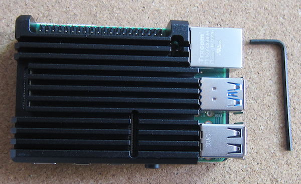
So when Pimoroni had a Raspberry Pi 4 4GB available, I bought one, a power supply and a (black) heat sink case.


There are two ways to detect the operation of buttons - polling and interrupt.
Polling involves checking the status of the button, which has to occur each time and can be missed if the program is busy elsewhere. It does have the benefit of conceptual simplicity.
Interrupts requires the program to be literally interrupted when the button is pressed, and code to be executed and then the program resumes its normal course. There are a number of complexities created by this method, especially if the task is complicated (things can be in the process of being changed when the interrupt occurs and so the results may not be predicted). There are additional complexities involved in the Micropython implementation (see the documentation here)
The PIMORONI Inky Pack (described here) is fitted with three buttons.

The objective is the display details of which button has been pressed.
Each button is attached to a GPIO pin (pins 12-14 on the Inky Pack) and can be created as a simple Pin object using the following code (this is for the button A on the Inky Pack).
pin1 = Pin(12,Pin.IN,Pin.PULL_UP)
To use interrupts, set the trigger and the callback handler function.
pin1.irq(trigger=Pin.IRQ_FALLING, handler=callback)
def callback(pin):
Supplies the Pin object to the code in the function.
Though the Pin object requires the pin id (in this case 12), it is not (currently 05/01/2023) possible to obtain the pin id from the Pin object directly.
However it is possible to check the equivalence of the supplied Pin against known pins:
def callback(pin):if(pin == pin1):print("Pin 1")
This means the same callback function can be used for all three pins, the equivalence check defines which pin is calling the callback function.
By using the code below, the following text is printed to the REPL console after the three buttons are pressed within the ten second cycle time of the loop and button B is pressed in the next loop.
cyclePin 1Pin 2Pin 3cyclePin 2
The Adafruit QT Py is a range of diminutive development boards. The QT Py pinout and shape is Seeed Xiao compatible and has castellated pads to allow it to be soldered to a PCB (note, some boards have components on the bottom of the board so will require a cut-out - this is one of them).
The boards have a QWIIC socket. It also has an RGB Neopixel.
Adafruit have released a version using the Raspberry Pi RP2040 processor (which requires a double-sided board to fit all the bits in the format).


Adafruit recommend CircuitPython but there is also an official MIcroPython port.However, there is little or no documentation on programming the board beyond that for a vanilla PICO.
Download the UF2 file from the MicroPython site. If you are downloading onto a Windows machine, right click on the downloaded file, select Properties and Unblock
Plug a USB A to USB C data cable into the board and the computer.
Hold the BOOTSEL button and press the RESET button.
The board will appear as a drive.
Copy the UF2 file to the board.
Once it has finished downloading, the board will restart.
The QT Py RP2040 has a Neopixel rather than the traditional LED on pin 13. This means that the normal Blink program does not work.
The CircuitPython UF2 specifically for the board has built in functions to operate the RGB Neopixel, and the board library has constants for the Neopixel pin.
I was unable to locate a Micropython example for the Blink program using a Neopixel.
Checking the pin-out https://learn.adafruit.com/assets/107201 shows that the RGB Neopixel is on pin 12, and the power for the Neopixel is on pin 11. To make the board more power efficient (useful for a battery powered application), the Neopixel can be unpowered in addition to not displaying a colour.
This requires both the Neopixel pin to be passed to the Neopixel constructor, and the power pin set to on.
https://micropython.org/download/ADAFRUIT_QTPY_RP2040/
https://www.adafruit.com/category/1005
https://learn.adafruit.com/adafruit-qt-py/overview
https://shop.pimoroni.com/products/adafruit-qt-py-rp2040?variant=39341945487443
https://learn.adafruit.com/adafruit-qt-py-2040/blink
https://docs.micropython.org/en/latest/rp2/quickref.html#neopixel-and-apa106-driver
https://docs.micropython.org/en/latest/rp2/quickref.html#i2s-bus