Introduction
The Adafruit QT Py is a range of diminutive development boards. The QT Py pinout and shape is Seeed Xiao compatible and has castellated pads to allow it to be soldered to a PCB (note, some boards have components on the bottom of the board so will require a cut-out - this is one of them).
The boards have a QWIIC socket. It also has an RGB Neopixel.
Adafruit have released a version using the Raspberry Pi RP2040 processor (which requires a double-sided board to fit all the bits in the format).
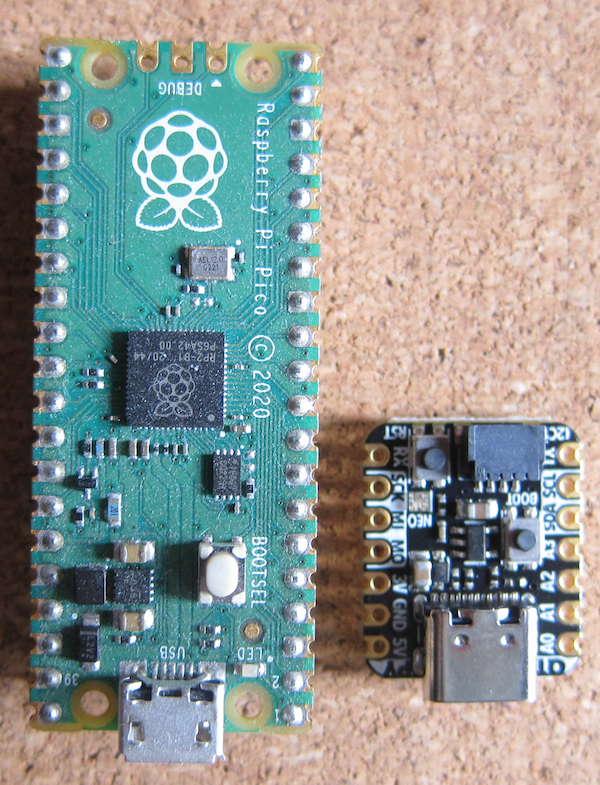
It is quite a lot smaller than the Raspberry Pi PICO.As you can see, the board, unlike the PICO is double sided. To solder it to another board, quite substantial cut outs would be required in the other board.
Adafruit recommend CircuitPython but there is also an official MIcroPython port.However, there is little or no documentation on programming the board beyond that for a vanilla PICO.
Installing MicroPython
Download the UF2 file from the MicroPython site. If you are downloading onto a Windows machine, right click on the downloaded file, select Properties and Unblock
Plug a USB A to USB C data cable into the board and the computer.
Hold the BOOTSEL button and press the RESET button.
The board will appear as a drive.
Copy the UF2 file to the board.
Once it has finished downloading, the board will restart.
Blink
The QT Py RP2040 has a Neopixel rather than the traditional LED on pin 13. This means that the normal Blink program does not work.
The CircuitPython UF2 specifically for the board has built in functions to operate the RGB Neopixel, and the board library has constants for the Neopixel pin.
I was unable to locate a Micropython example for the Blink program using a Neopixel.
Checking the pin-out https://learn.adafruit.com/assets/107201 shows that the RGB Neopixel is on pin 12, and the power for the Neopixel is on pin 11. To make the board more power efficient (useful for a battery powered application), the Neopixel can be unpowered in addition to not displaying a colour.
This requires both the Neopixel pin to be passed to the Neopixel constructor, and the power pin set to on.
Code
import machine
import neopixel
# Set up a single Neopixel
pin = machine.Pin(12, machine.Pin.OUT)
pixel = neopixel.NeoPixel(pin, 1)
pixel.brightness = 0.3
# Set the power pin high to activate the Neopixel
power_pin = machine.Pin(11, machine.Pin.OUT)
power_pin.on()
def set_pixel(rgb):
# Set the first pixel to rgb
pixel[0] = rgb
# Write the setting to the Neopixel
pixel.write()
while True:
# Set the first pixel to Red
set_pixel((255, 0, 0))
time.sleep(0.5)
# Set the first pixel to off
set_pixel((0, 0, 0))
time.sleep(0.5)
print("Blink!")
References
https://micropython.org/download/ADAFRUIT_QTPY_RP2040/
https://www.adafruit.com/category/1005
https://learn.adafruit.com/adafruit-qt-py/overview
https://shop.pimoroni.com/products/adafruit-qt-py-rp2040?variant=39341945487443
https://learn.adafruit.com/adafruit-qt-py-2040/blink
https://docs.micropython.org/en/latest/rp2/quickref.html#neopixel-and-apa106-driver
https://docs.micropython.org/en/latest/rp2/quickref.html#i2s-bus


