Sunday, 29 December 2024

Pimoroni Plasma 2350

Raspberry Pi recently released the RP2350 microcontroller. There was a shortage of the corresponding Pico 2 development board, but other board manufacturers certainly filled the gap.

One of them was Pimoroni with a number of interesting offerings.

One of them is the Plasma 2350 Neopixel strip controller.

I already had a set of the RGB LED Star Wire 66 Neopixel strips, so I just bought the board.

The board is fully assembled and just requires the use of a jeweller's type screwdriver to attach the wires from the NeoPixel strip to the board using the terminal block. One thing to note is that unlike the Plasma Stick 2040W, the Plasma 2350 has a four connector terminal block. As you can see, the connections to use are 5V, Dat[a] and negative.

The board has one QWIC/STEMMA I2C connector, an on-board NeoPixel, three buttons (reset, boot and user button) and a connector labelled SP/CE. The latter is an SPI connector standard allowing higher speed connections to the board (such as WIFI).

What it does not have is WIFI or Bluetooth onboard (a later variant does but does not have the SP/CE connector, a Raspberry Pi RM2 Wireless module is directly wired to the board.)

Code

So to use the board and the LED string, some code is required.
This is the code for the main.py file.
The plasma2040 module in plasma works with the Pasma 2350.
The user interface is very simple. Pressing the User Button A cycles through the available light options.
The specific display uses Pythons' polymorphism to handle the basic operations. The method update() updates the display and is triggered (in this case) every half a second.
The light_show_base class (and its subtypes) determine what happens during the update. That code is in a separate file.

main.py

import plasma
from light_show_base import RGBElement, light_show_base, light_show_static_seven, light_show_static_seven_reverse, light_show_alternate
from plasma import plasma2040
from time import sleep
from pimoroni import RGBLED
# Set how many LEDs you have
NUM_LEDS = 66

led = RGBLED(16, 17, 18) 

# WS2812 / NeoPixel™ LEDs
led_strip = plasma.WS2812(NUM_LEDS, 0, 0, plasma2040.DAT)

# Start updating the LED strip
led_strip.start()

display = light_show_base(led_strip, NUM_LEDS, led)
a_button = machine.Pin(12, machine.Pin.IN, machine.Pin.PULL_UP)

selected_pattern = 0

while True:
    display.update()
    if a_button.value() == 0:
        selected_pattern = selected_pattern + 1
        if selected_pattern > 5:
            selected_pattern = 0

        if selected_pattern == 0:
            display = light_show_base(led_strip, NUM_LEDS, led)
        elif selected_pattern == 1:
            display = light_show_static_seven(led_strip, NUM_LEDS, led)
        elif selected_pattern == 2:
            display = light_show_static_seven_reverse(led_strip, NUM_LEDS, led)
        elif selected_pattern == 3:
            display = light_show_alternate(led_strip, NUM_LEDS, led, RGBElement(255,0,0), RGBElement(0,255,0))
        elif selected_pattern == 4:
            display = light_show_alternate(led_strip, NUM_LEDS, led, RGBElement(0,0,255), RGBElement(255,255,0))
        elif selected_pattern == 5:
            display = light_show_alternate(led_strip, NUM_LEDS, led, RGBElement(0,255,0), RGBElement(255,255,255))
        print(selected_pattern)

    sleep(0.5)
    

light_show_base.py

The file contains two main classes: RGBElement and light_show_base.
There are also subclasses of class light_show_base, inheriting from light_show_base.
class RGBElement:
    def __init__(self,red, green,blue):
        self.red = red
        self.green = green
        self.blue = blue
    def __str__(self): 
        return f"{self.red} {self.green} {self.blue}"
        
class light_show_base:
    def __init__(self, led_strip, num_leds, rgb_led):
        # Device specific settings
        self.led_strip = led_strip
        self.rgb_led = rgb_led
        self.num_leds = num_leds
        
        # Chosen colour
        self.current_colour = 0
        
        # Base set of colours
        self.white = RGBElement(255,255,255)
        self.yellow = RGBElement(255,255,0)
        self.magenta = RGBElement(255,0,255)
        self.red = RGBElement(255,0,0)
        self.cyan = RGBElement(0,255,255)
        self.green = RGBElement(0,255,0)
        self.blue = RGBElement(0,0,255)
        self.black = RGBElement(0,0,0)
  
        # List of colours
        self.colours = [
            self.white,
            self.yellow,
            self.magenta,
            self.red,
            self.cyan,
            self.green,
            self.blue,
            self.black
            ] 

            
    def update(self):
        if self.current_colour == len(self.colours) - 1:
            self.current_colour = 0
        else:
            self.current_colour = self.current_colour + 1

        rgb_colour = self.colours[self.current_colour]
        self.rgb_led.set_rgb(rgb_colour.red, rgb_colour.green, rgb_colour.blue)
        for i in range(self.num_leds):
            self.led_strip.set_rgb(i, rgb_colour.green,rgb_colour.red, rgb_colour.blue)
        
class light_show_static_seven(light_show_base):
    def __init__(self, led_strip, num_leds, rgb_led):
        super().__init__(led_strip, num_leds, rgb_led)
        self.colour_strip = []
        ix = 0
        for i in range(self.num_leds):
            self.colour_strip.append(self.colours[ix])
            if ix == len(self.colours) - 1:
                ix = 0
            else:
                ix = ix +1
                
    def change_colours(self):
        last_colour = self.colour_strip[1]
        for i in range(self.num_leds):
            if i > 1:
                self.colour_strip[i - 1] = self.colour_strip[i]
        self.colour_strip[self.num_leds - 1] = last_colour
            
    def update(self):
        for i in range(self.num_leds):
            rgb_colour = self.colour_strip[i]           
            self.led_strip.set_rgb(i, rgb_colour.green,rgb_colour.red, rgb_colour.blue)
        rgb_colour = self.colour_strip[1] 
        self.rgb_led.set_rgb(rgb_colour.red, rgb_colour.green, rgb_colour.blue)

        self.change_colours()

class light_show_static_seven_reverse(light_show_static_seven):
    def __init__(self, led_strip, num_leds, rgb_led):
        super().__init__(led_strip, num_leds, rgb_led)

    def change_colours(self):
        last_colour = self.colour_strip[self.num_leds-1] 
        for i in range(self.num_leds-1):
            ix = self.num_leds - i
            print(ix)
            if ix < self.num_leds-1: 
                self.colour_strip[ix + 1] = self.colour_strip[ix]
        self.colour_strip[1] = last_colour            
        
class light_show_alternate(light_show_base):
     def __init__(self, led_strip, num_leds, rgb_led, led_one, led_two):
        super().__init__(led_strip, num_leds, rgb_led)
        self.led_one = led_one
        self.led_two = led_two

     def change_colours(self):
        temp = self.led_one
        self.led_one = self.led_two
        self.led_two = temp


     def update(self):
        led_one = self.led_one
        led_two = self.led_two
        self.rgb_led.set_rgb(led_one.red, led_one.green, led_one.blue)
        for i in range(self.num_leds/2):
            self.led_strip.set_rgb(i * 2, led_one.green,led_one.red, led_one.blue)
            self.led_strip.set_rgb(i * 2+1, led_two.green,led_two.red, led_two.blue)
        self.change_colours()

References


Sunday, 24 November 2024

Adafruit RP2040 Prop-Maker Feather - Staser sound effect

This uses the Prop-Maker Feather'’s I2S audio amplifier to generate a sound effect, in this case a Gallifreyan Staser sound effect.


For testing purposes, the sound is triggered by the use of the Boot button on the board (the Boot button on the Prop-Maker Feather is connected to GPIO7 and named board.Button in CircuitPython)

For use as a prop, the trigger would be wired to the Button terminal and the Ground terminal shared with the NeoPixel.

Getting your sound effect.

The Prop-Maker Feather requires a PCM 16-bit Mono WAV files at a sample rate of 22KHz. This can be created using Audicity by following the Adafruit instructions.

Code

# Staser sound effect
import board
import digitalio
import time
import neopixel
import random
import audiocore
import audiobusio
import audiomixer
import pwmio
import keypad

keys = keypad.Keys((board.BUTTON,), value_when_pressed=False, pull=True)

# One of the features of the prop-maker is that the Neopixel
# (and the amplifier and the speaker) can be switched on and off
external_power = digitalio.DigitalInOut(board.EXTERNAL_POWER)
external_power.direction = digitalio.Direction.OUTPUT
external_power.value = True

audio = audiobusio.I2SOut(board.I2S_BIT_CLOCK, board.I2S_WORD_SELECT, board.I2S_DATA)

def play(filename, audio):
    # i2s playback
    wave_file = open(filename, "rb")
    wave = audiocore.WaveFile(wave_file)
    mixer = audiomixer.Mixer(voice_count=1, sample_rate=22050, channel_count=1,
                         bits_per_sample=16, samples_signed=True)
    audio.play(mixer)
    mixer.voice[0].play(wave, loop=False)
    mixer.voice[0].level = 0.5
    print("Fire")
    wave_file

while True:
    event = keys.events.get()
    # event will be None if nothing has happened.
    if event:
        if event.pressed:
            play("staser.wav",audio)

print("Done")

References

https://learn.adafruit.com/adafruit-rp2040-prop-maker-feather/overview

https://learn.adafruit.com/key-pad-matrix-scanning-in-circuitpython/keys-one-key-per-pin

https://learn.adafruit.com/microcontroller-compatible-audio-file-conversion

https://learn.adafruit.com/lightsaber-rp2040/code-the-lightsaber


Adafruit RP2040 Prop-Maker Feather

The Adafruit RP2040 Prop-Maker Feather is an Adafruit Feather format board using the Raspberry Pi RP2040 processor with 8MB of QSPI FLASH with a terminal block connector at one end, QWIC/STEMMA connector, Servo connector and adjacent to the USB type C connector a battery connector (with charging capability). It can be used without any soldering.


There is a slightly more in-depth discussion here.

The terminal block has three connections for the NeoPixels (5V, ground and data), two for a 4-8 ohm speaker and one for a button.

Assembly

This set up is going to use a 500mm strip of 332 LED per metre ultra dense strip.

It is supplied with a female connector and a matching male connector with wires to connect to the Feather’s terminals.

Unfortunately, due to not completely comprehending the operation of the NeoPixel driver, I went through a number of iterations on connection, including removing the connector on the strip before finally realising that the NeoPixel driver is by default OFF, and a pin needs to be set to make it (and the speaker driver) live. Once that was set and the wires appropriately connected everything was fine.

Installation

CircuitPython is derived from MicroPython and makes the device appear as a USB storage device on the host computer.

This means that any editor can be used to edit the CircuitPython source as long as when it saves, it saves everything to the device.

I use a slightly different method, I have a simple Visual Studio program that I use to copy all the required files to the device - and develop using Visual Studio Code. This means that there is always a copy of the code on the laptop in the event that the device becomes unreadable.

The alternative is to use an IDE like MU.

Download the latest version of CircuitPython for the board from the CircuitPython site.

Connect the Prop-Maker Feather to the computer with a known good data (not charge only cable).

The Prop-Maker Feather has a Reset and a Boot Select button. This makes entering the Bootloader a lot easier tan having to unplu and plug the device in while holding down a tiny button.

Hold down the BOOT button and while continuing to hold it, press and release the reset button. Keep holding the BOOT button until a RPI-RP2 drive on the computer.

Copy and paste the UF2 file into the drive. When it has finished copying, the Feather will reboot.

Coding

This program repeatedly through runs the NeoPixel strip through a number of colours. The onboard LED is flashed during each cycle.

# Imports

import board

import digitalio

import time

import neopixel


# Use the builtin LED as a pulse

led = digitalio.DigitalInOut(board.LED)

led.direction = digitalio.Direction.OUTPUT


# Set a list of colour combinations

COLORS = (

    (255,   0,   0),

    (  0, 255,   0),

    (  0,   0, 255),

    (255, 255,   0),

    (255,   0, 255),

    (  0, 255, 255),

)

# Set up Neopixels

# This is for a 0.5m Ultra-dense RGB Micro LED Strip with 332 LEDs per metre

num_pixels = 165

pixels = neopixel.NeoPixel(board.EXTERNAL_NEOPIXELS, num_pixels, auto_write=True)

pixels.brightness = 0.02

# One of the features of the prop-maker is that the Neopixel 

# (and the amplifier and the speaker) can be switched on and off 

external_power = digitalio.DigitalInOut(board.EXTERNAL_POWER)

external_power.direction = digitalio.Direction.OUTPUT

external_power.value = True


# Loop indefinitely

while True:

    # Loop through the colour list

    for color in COLORS:

        # Set the built in LED on

        led.value = True

        time.sleep(0.5)

        # Set each pixel in turn

        for i in range(num_pixels):

            pixels[i] = color

        pixels.show()

        # Set the built in LED off

        led.value = False

        time.sleep(0.5)

Here is the device in action.


References

https://shop.pimoroni.com/products/adafruit-rp2040-prop-maker-feather-with-i2s-audio-amplifier?variant=41128910454867

https://shop.pimoroni.com/products/neon-like-rgb-micro-led-strip?variant=39395564585043

https://circuitpython.org/board/adafruit_feather_rp2040_prop_maker/

https://circuitpython.org/libraries

https://learn.adafruit.com/adafruit-rp2040-prop-maker-feather/overview

https://learn.adafruit.com/lightsaber-rp2040/code-the-lightsaber


Sunday, 10 November 2024

Raspberry Pi Hailo AI HAT+

Introduction

The Raspberry Pi AI HAT+ add-on board has a built-in Hailo 13 (8L) and 26 (8) tera-operations per second (TOPS) AI accelerator. 


Data transfer is via a PCIe interface (so is only compatible with Raspberry Pi 5s, not earlier models).

The Raspberry Pi 5 will detect the presence of the Hailo Accelerator and can use the Neural Processing Unit for supported AI tasks, including the built in O/S rpicam-apps post processing tasks.

What you need

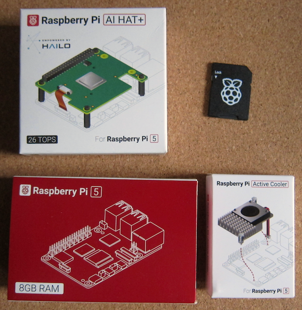
You will need a Raspberry Pi 5, an Active Cooler, the Raspberry Pi AI HAT+ and a suitably loaded MicroSD card.

Raspberry Pi have recently started to supply high-speed preloaded MIcro SD cards.

Installation

This installation follows the general procedure described in the instructions.

However, if you wish to use a PiBow Coupe case with this build, ensure that you begin fitting the case components before installing the Active Cooler as it is not recommended to remove a previously installed Active Cooler.

So I have a PiBow Coupe case for another Raspberry Pi 5 (luckily I also ordered a Raspberry Pi Bumper case at the same time).


Install the Active Cooler

The Raspberry Pi 5 tends to run hot, so the Active Cooler (or a case with a fan) is recommended.

Now, probably the board and the SD card should be tested before installing the cooler (as removal of the active cooler is not recommended and likely to be messy).

Remove the backing paper from the Active Cooler, this shows the heat transfer pads.

Before adding the Active Cooler, remove the blanking piece from the Fan connector on the Raspberry Pi board. It is possible to remove when the Active Cooler is attached, but it is more difficult.

Orientate the Active Cooler above the Raspberry Pi board so the fan enclosure is towards the USB and Ethernet enclosures. Align the two pins with the corresponding holes in the board and ensure that the fan cable is clear. Once aligned correctly, gently push the end of the pins through the board. The spring clips will hold the pins in place.


Initial Software Set up

First ensure that the Raspberry Pi has a suitable SD card installed. I ordered a pre-loaded example

Boot and configure as per normal.

I have found that the WiFi is not detected, so had to miss out on the O/S update until the initial setup was complete and then added the WiFi. There was a slight issue with the first software update which required a call to dpkg to clear up.

As it was a clean new install the following two steps may not have been required but were undertaken.

sudo apt update

sudo apt full-upgrade

The boards firmware needs to have the required updates so run:

sudo rpi-eeprom-update

Check date, if after 6 December 2023 it is fine otherwise use raspi-config to update the bootloader to the latest version.

Then run 

sudo rpi-eeprom-update -a

Reboot (sudo reboot).

Install the AI HAT+

The AI HAT+ comprises the board itself, an extended header (of which more anon) and a fixing kit.


Note that the ribbon cable is taped to the board. Remove the tape before proceeding (carefully).

The instructions recommend removing the ribbon cable from the board, but neglect to inform you how to release it. I managed to leave it in place.

Align the stacking header with the pins on the GPIO, there is no orientation, just make sure that the pins are aligned with the holes. Push firmly down.

There are four short and four long screws included in the kit, the instructions show the smaller screws in use at the bottom, but because I was using the Bumper Case I used the longer ones, passing through the holes in the case. The spacers were then screwed into screws (not too tight).

It is at this point that the instructions suggest inserting the ribbon cable into the PCIe socket on the board. 

Lift the cover on the PCIe connector and insert the end of the ribbon cable. If you have left the cable in the board, then you will probably need to move on to attaching the AI HAT+ to the spacers before fitting the cable to the Raspberry Pi.

Use the remaining screws to attach the board.


I mentioned the stacking header earlier.
I was expecting the pins to pass all the way through the soclet on the AI HAT+, unfortunately the 16mm extended header supplied only just passes through, there is insufficient remaining header to add an additional HAT on top.
This might [possibly be by design, but in that case I would have expected a conventional socket to be fitted to the AI HAT+ board rather than a pass through one.


Fit the cable to the board.

Software installation

There is a recommendation that the PCIe interface is set to Gen 3.0. There are instructions here.

Install dependences

sudo apt install hailo-all

Reboot

Check everything is working with the following command:

hailortcli fw-control identify

If you get an error 13, check that the cable is inserted correctly.

Next steps

Test the board with a USB camera (I am not intending to use the board with a camera so I have not installed one).

That is for another post.

References:

https://shop.pimoroni.com/products/pibow-5?variant=41045302542419

https://shop.pimoroni.com/products/raspberry-pi-5?variant=41044580171859

https://shop.pimoroni.com/products/raspberry-pi-5-active-cooler

https://shop.pimoroni.com/products/raspberry-pi-ai-hat?variant=53502129701243

https://shop.pimoroni.com/products/microsd-card-with-raspberry-pi-os?variant=31703694245971

https://shop.pimoroni.com/products/raspberry-pi-5-bumper


https://www.raspberrypi.com/news/raspberry-pi-ai-hat/

https://www.raspberrypi.com/products/ai-hat/

https://cdn.shopify.com/s/files/1/0174/1800/files/Raspberry_Pi_AI_HAT_product_brief.pdf?v=1729683532

https://www.raspberrypi.com/documentation/accessories/ai-hat-plus.html

https://www.raspberrypi.com/documentation/computers/ai.html

https://www.raspberrypi.com/documentation/computers/raspberry-pi.html#pcie-gen-3-0


https://en.wikipedia.org/wiki/AI_accelerator

https://en.wikipedia.org/wiki/Hailo_Technologies


Saturday, 27 January 2024

Raspberry PI 5 with NVME Base and SSD

 Pimoroni have recently released a base to interface a Raspberry Pi 5 to a Solid State Drive.

Components

Raspberry Pi 5 with 8GB of RAM.

A Raspberry Pi 5 Active Cooler (fan and heat sink).


The Active Cooler comes complete with pre-fitted heat sink pads.
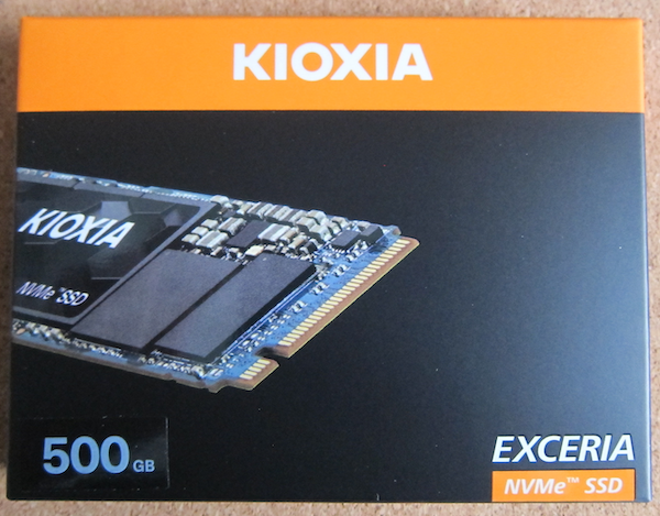
A 500GB SSD. 

The Pimoroni NVME base.
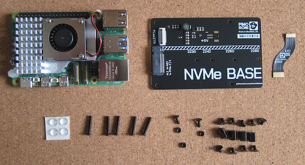
The NVME pack contains the base plate itself, a pack of crews and nuts, a ribbon cable and some self-adhesive feet.
Of course you need a power supply.

Assembling the Raspberry Pi 5 with the active cooler

Take the Raspberry Pi 5 out of the box (remember to earth your self before opening the box).
Take the Active Cooler out of its box and check the power cable.
Remove the cap from the fan socket.

Remove the backing paper from the heat sink.
Check the operation of the spring-loaded attachment pins.

Align the pins with the relevant holes in the Raspberry Pi board.
When they are aligned, push the pins through the cooler board until they are attached to the Raspberry Pi board. Ensure alignment before releasing the pins so the heat sink material adheres to the required components. 

This is definitely not something to do when it is very warm as it makes the heat sink material very sticky.

Plug the cooler power lead into the Raspberry Pi board.

Create the OS SD card

The latest installer allows you to select the hardware, in this case a Raspberry Pi 5, as well as the operating system.

The NVME base requires 64-bit Raspberry Pi OS.

Select the 64bit Raspberry Pi OS.

Image the SD card.

Once the OS is ready, slot the SD card in and boot.

Finish the set up for the OS including a full update..

Building the NVME base

Once the Raspberry Pi is updated, shut it down and remove the power supply.
Place the Raspberry Pi 5 and the contents of the NVME pack on your work space.
Check the components:
  • NVMe Base PCB with M.2 Slot (M-Key)
  • 'PCIe Pipe' Flat Flex Cable
  • 4x Rubber feet
  • M2 bolt and 2x nuts for SSD mounting
  • 4x 7mm M2.5 standoffs for base mounting
  • 8x short M2.5 bolts for base mounting 
  • 4x long M2.5 bolts for 'pass-through' mounting with a HAT
The pack is suppllied with a number of spares, just in case.

Fit the short M2.5 bolts through the base and add the stand-offs.


Carefully remove the SSD from the packaging. In this case, there are instructions in the box showing how to remove the SSD (you use one of the finger holes and rotate it out of the plastic carrier). 

Take the M2 bolt and fit to the base for the size of SSD. Fix in place with one of the nuts.

Take the SSD drive and slot into into the slot on the board. Ensure the SSD in aligned properly and square to the connector. Fix in place with the second nut.

Take the Raspberry Pi board. Gently lift the cover on the PCIE connector.

Take the ribbon cable. The image ill face outwards when fully assembled and the Pi end is the smaller (so the text is the right way up when the NVME base is at the bottom.

Hold the cable in place (copper side towards the centre of the board) and push down the latches.

Turn the Pi upside down and bring the NVME base in.

On the NVME board, flip up the connector. Fit the ribbon cable. Once it is correcly aligned, flip the latch down.

Now screw the two boards together carefully.


Turn the Pi - NVME board sandwich (with its SSD filling) upside down.
Apply the self adhesive feet. The left hand end is easy as they can go in the top and bottom corners. The right hand ones can go just in-board of the screws.

Software installation

Switch on your Raspberry Pi.

Log in as normal (you should have already configured the SD card earlier).

The Raspberry Pi needs to have the latest updates including firmware. The normal update should  work, but you can force the update via  sudo raspi-config. Update the firmware using sudo epi-eeprom-update.

You can format the the SSD using the Raspberry Pi Imager. It should allow you to import the settings from the SDD card (locale, WiFi etc).

Once that has completed run sudo raspi-config in a terminal window.

Go to the Advanced section and change the boot order to boot from the SSD.

Reboot.

The Raspberry Pi will boot from the SSD.

Shut down, and carefully remove the SD card and put it in a safe place.

References

Raspberry Pi 5

https://shop.pimoroni.com/products/raspberry-pi-5?variant=41044580171859

Raspberry Pi 5 Active cooler

https://shop.pimoroni.com/products/raspberry-pi-5-active-cooler

NVME Base

https://shop.pimoroni.com/products/nvme-base?variant=41219587178579

Assembling the NVME Base video

https://www.youtube.com/watch?v=odG7FbptgWQ